

R
Richard JonesJul 31, 2025
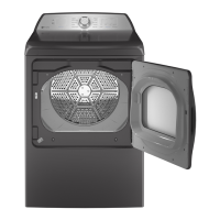
What to do if my GE Profile PTDS650EM Dryer displays error E6?
- Jjoseph48Jul 31, 2025
If your GE Dryer displays error code E6, it indicates a door switch malfunction. You should check and replace the door switch if necessary.