EasyManuals Logo

GE Power Break II User Guide

GE Power Break II
27 pages
To Next Page IconTo Next Page
To Previous Page IconTo Previous Page
Page #10 background imageLoading...
Page #10 background image
Power
Break
®
II
Circuit
Breakers
Chapter
2
.
Operation
2
-
1
Standard
Features
Power
Break
II
circuit
breakers
are
equipped
with
the
following
standard
features
.
The
letters
are
keyed
to
the
breaker
photographs
in
Figures
3
and
4
.
A
Indicator
:
ON
-
Red
OFF
-
Green
B
Indicator
:
CHARGED
-
Yellow
DISCHARGED
-
White
C
ON
button
D
OFF
button
E
Manual
charging
handle
F
Integral
36
-
point
terminal
block
(
12
auxiliary
switches
,
A
-
B
type
)
G
Integral
36
-
point
terminal
block
(
all
other
connections
)
H
Sealable
hinged
cover
I
Cover
mounting
screws
(
4
)
K
Trip
Unit
interchangeable
rating
plug
L
Test
set
connection
port
M
Standard
padlock
provision
N
Dust
-
resistant
ventilation
slots
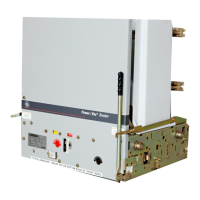
Figure
4
.
Front
of
breaker
,
with
Trip
Unit
and
top
cover
removed
.
2
-
2
Operating
Instructions
Sequence
of
Operations
The
sequence
of
operations
that
may
be
performed
on
the
circuit
breaker
are
listed
in
Table
3
.
Refer
fc
>
Chapter
3
for
information
about
accessory
opera
-
tion
.
Figure
3
.
Front
of
breaker
,
showing
location
of
standard
features
.
3
Courtesy of NationalSwitchgear.com

Other manuals for GE Power Break II

Questions and Answers:

Question and Answer IconNeed help?

Do you have a question about the GE Power Break II and is the answer not in the manual?

GE Power Break II Specifications

General IconGeneral
BrandGE
ModelPower Break II
CategoryCircuit breakers
LanguageEnglish

Related product manuals