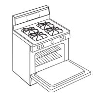
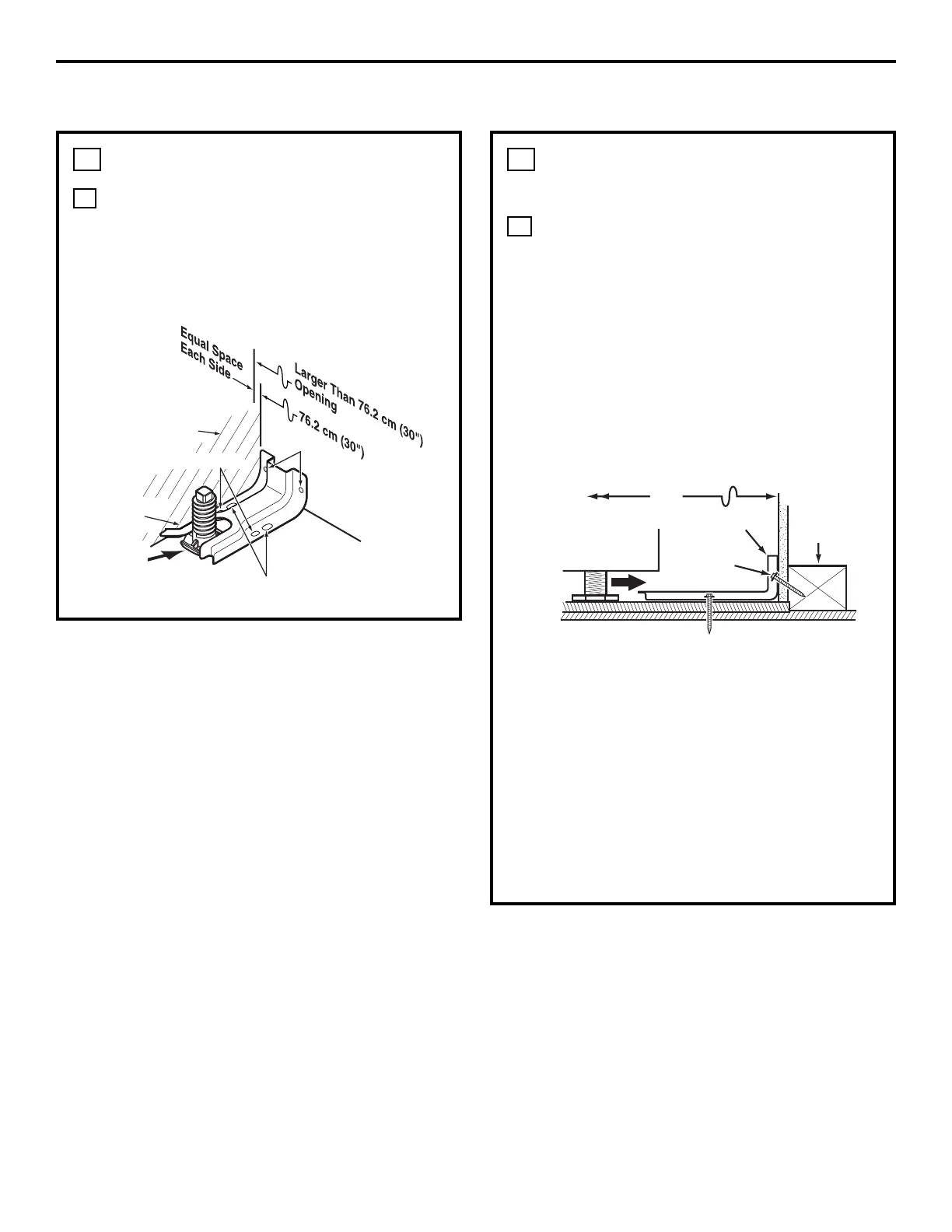
INSTALL THE ANTI-TIP BRACKET
LOCATE THE BRACKET
a. Decide whether the bracket will be
installed on the right or left side of the
range opening.
b. Place the bracket as shown in Fig. 1.
A
12
Rear
leveling leg
Wall
FLOOR-CONCRETE
9
Installation Instructions
INSTALL THE RANGE
INSTALL THE ANTI-TIP BRACKET
(cont.)
INSTALL THE BRACKET IN WOOD
OR CONCRETE
INSTALLATION—WOOD CONSTRUCTIONS
a. Locate the centers of the 4 holes identified
in Fig. 1 as Floor–Wood and Wall.
b. Drill a 1/8″ pilot hole through the
pre-marked areas. Note the angle of the
wall screw in Fig. 2.
c. Mount the Anti-Tip bracket with the
4 screws provided.
INSTALLATION—CONCRETE CONSTRUCTIONS
a. For concrete installation, you will need
two 1/4″ x 1-1/2″ lag screws and two sleeve
anchors.
b. Locate the center of the 4 holes identified
in Fig. 1 as Floor–Concrete and Wall.
Drill the recommended size holes in each.
c. Install the sleeve anchors into the
predrilled concrete holes and install the
lag and wall screws through the Anti-Tip
bracket. Make sure the screws are securely
tightened.
B
12
FLOOR-WOOD
Bracket
side
Adjacent
cabinet
Top front
edge of
countertop
25″
Wall plate
Screw
must enter
wood or
metal
Bracket
Fig. 1
Fig. 2