Chapter 4. Installation
20 QuickPanel+ User’s Manual–November 2013 GFK-2847
Figure 5. Mounting Holes
Installation Notes:
■ To avoid gasket degradation, limit repeated insertions or removals of the unit and
retightening of the mounting clips. For full protection, always use a fresh gasket.
Replacement gaskets can be ordered using the part number listed in Appendix B.
■ The unit will not fit through the cutout with any cables connected, or with the power
supply plug inserted in the socket.
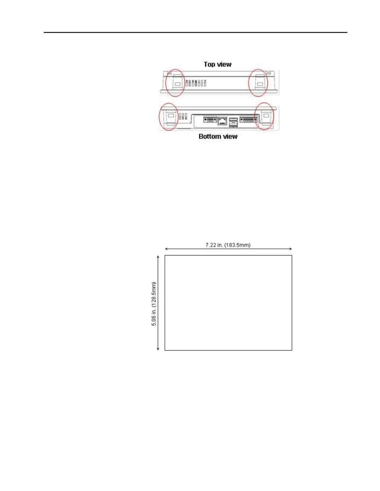
1. Cut an opening in the panel according to the specifications in the diagram below. Panel
thickness supported: 1.0mm to 5.0mm.
Figure 6. Panel Cutout Dimensions for 7” QuickPanel+
2. Slide the QuickPanel+ into the mounting panel cut-out.