EasyManua.ls Logo

GE SPS-48V User Manual

GE SPS-48V
12 pages
To Next Page IconTo Next Page
Page #1 background imageLoading...
Page #1 background image
SPS J200703 L005 Quick Start Guide
1
Document 850052515 r02 2019 April
GE
Critical Power
SPS –48V Slimline Power Shelf
Models: J2007003L005 - alpha suffixes per Slimline Power System Brochure
Quick Start Guide
Document xxxxxxxxxx R01 2017 August
1
No vertical spacing is required, allow a minimum 2”, inch clearance at back of shelf for rectifier airflow.
Tools required:
Wire cutters and strippers
Screwdrivers - Philips #1 and #2, Flat
small
Cable crimpers
Step 1 - Mount Shelf
1. Reposition mounting ears as required - 3 screws each. (Reverse ears for 5setback.)
Torque to 10 in-lb. (1.2 Nm) - Phillips screwdriver.
2. Attach shelf to the frame using a minimum of four screws (two on each side) - 12-24 (provided).
Torque to 35 in-lb. (4 Nm) - 5/16” socket.
Step 2 - Connect Chassis Ground and DC Reference (CO) Ground
Lug Landings: #10 double-hole on 5/8-inch center (lugs not provided)
Some applications may rely on frame mounting screws for chassis ground, omitting the chassis ground wire.
Some applications may use the Chassis Ground strap, using a single wire for both chassis ground and DC
reference ground.
Minimum 10 AWG wire is recommended.
Torque 10-32 screws to 30 in-lb. (3.4 Nm) - 5/16” socket.
Question and Answer IconNeed help?

Do you have a question about the GE SPS-48V and is the answer not in the manual?

GE SPS-48V Specifications

General IconGeneral
BrandGE
ModelSPS-48V
CategoryPortable Generator
LanguageEnglish

Summary

Step 1: Mount Shelf

Mounting Ears Adjustment

Adjust mounting ears for shelf placement. Torque to 10 in-lb (1.2 Nm) with a Phillips screwdriver.

Shelf Attachment to Frame

Secure shelf to frame using four 12-24 screws. Torque to 35 in-lb (4 Nm) using a 5/16" socket.

Step 2: Connect Chassis Ground and DC Reference

Grounding Connections

Connect chassis ground strap or wire for DC reference. Use 10 AWG wire; torque 10-32 screws to 30 in-lb.

Step 3: Connect AC Input

AC Power Cord Installation

Connect AC power cords (C13/C19) and secure with retention clamps. Ensure AC power is OFF for blunt cuts.

Step 4: Connect DC Output and Batteries

Verify Battery Voltage and Polarity

Use a voltmeter to confirm battery voltage and polarity before connecting. Ensure breaker is OFF.

Load and Return Wire Connections

Strip wires (0.4 in), torque to 6.5 in-lb (0.75 Nm), pull to verify, and insert terminal block.

Step 5: Install Breakers and Fuses

Breaker Installation Procedure

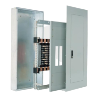
Install breakers OFF, orient ON-up, secure cover, then turn breakers ON. Use 30A max breakers.

GMT Fuse Installation

Insert GMT style fuses fully into position, oriented correctly. Maximum fuse rating is 15A.

Step 8: Install Signal and Communications Cables

Alarm and Input Cable Connections

Connect J1-2Alarms/Inputs to office alarms and signals. Refer to Alarm Connections section.

LAN Network Connection

Connect J5 LAN port to the Ethernet network for system management and configuration.

Step 10: Install Rectifiers

Rectifier Insertion and Securing

Push rectifier firmly into slot. Tighten thumb screw until seated. RUN LED indicates communication status.

Step 11: Initial Start Up

System Power-Up and Checks

Verify all connections, turn on AC breakers. Monitor for alarms and adjust settings as needed.

Information: Branch Protection Details

Branch Protection Ratings

Table showing North America and CE branch protection limits (15A, 20A) for different shelf models.

Information: Rectifier Options

Rectifier Model Specifications

Details rectifier options, input voltage/current, and output power (W) and current (A).

Information Alarm Connections

Alarm Connector Pinout Details

Provides detailed pinout for J1 and J2 connectors, mapping pins to controller variants and functions.

Specifications and Application

Product Specifications Reference

Refer to the Slimline Power System Brochure for detailed specifications and ordering information.

Reference Documents

Related Product Manuals

Lists key documents like the Galaxy Pulsar Edge Quick Start Guide and Product Manual.

Safety Statements

General Installation Safety

Adhere to rules, regulations, use correct connectors, and ensure electrical securing for safe installation.

Precautions

Equipment Handling Precautions

Handle equipment with qualified personnel. Disconnect batteries, verify grounding, use insulated tools.

Personal Safety Measures

Wear safety glasses, appropriate PPE, test circuits, and use ESD straps when handling components.

Related product manuals