Do you have a question about the GE 040374 and is the answer not in the manual?
Explains safety symbols, signal words, and their meanings.
Highlights critical warnings regarding CO poisoning, electrical hazards, and fuel risks.
Defines the roles and duties of the owner and installer during setup.
A comprehensive list of tasks for proper generator system installation.
Details on cold weather operation needs and included generator components.
Specifies minimum distances for exhaust, structure, and overhead clearances.
Identifies potential CO entry points and placement strategies to prevent exposure.
Provides guidelines for generator placement to reduce the risk of fire ignition.
Illustrates various minimum installation distances for safe operation and airflow.
Covers additional location criteria and NFPA 37 requirements for placement.
Pinpoints the physical locations of electrical and fuel inlet ports on the generator.
Instructions for safely lifting the generator and securing it with anchoring.
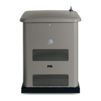
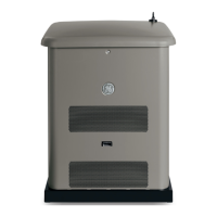
Identifies the front panel and the components it provides access to.
Outlines mandatory rules and considerations for installing gaseous fuel supply lines.
Specifies fuel pressure needs and how altitude affects power.
Provides references for selecting appropriate fuel pipe sizes.
Step-by-step guide for converting the generator to use LP vapor fuel.
Details the function and connections of various terminal blocks on the control board.
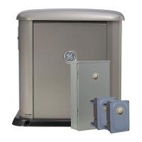
Explains how to connect power output and communication to the transfer switch.
Describes the generator's AC connection system and neutral bonding.
Details utility and generator power connections, including conduit use.
Describes buttons, ports, fuse, and digital display on the control board.
Explains how to navigate menus and the purpose of each button.
Details the key sequences to enter different programming modes.
Describes the messages shown in Automatic Mode (READY, ON, SERVICE CODE).
How to access and view system data like run time, date, and software version.
Explains how the generator's sensors detect and report service conditions.
Specifies oil type, battery voltage, CCA, and installation instructions.
Describes the generator's automatic response to utility power loss and restoration.
Instructions for scheduling and changing the generator's weekly exercise cycle.
Identifies monitor parts, LEDs, and their operational meaning.
Guidance on antenna placement and initial setup for the wireless monitor.
Explains LED indicators for generator ready, power, and service needed states.
Lists service codes and emphasizes the final installation inspection.
Provides schematic and wiring diagrams for the 10kW generator model.
Provides schematic and wiring diagrams for the 8kW generator model.
| Brand | GE |
|---|---|
| Model | 040374 |
| Category | Portable Generator |
| Language | English |