8-6 T35 TRANSFORMER PROTECTION SYSTEM – INSTRUCTION MANUAL
DIFFERENTIAL CHARACTERISTIC TEST EXAMPLES CHAPTER 8: COMMISSIONING
8
3. When test setup is correct, the relay displays the following differential and restraint currents, and the element does
not operate.
8.2.2.3 Minimum pickup test
Reduce the restraint current I
r
to a value lower than 0.67 pu (the restraint corresponding to the intersection of Slope 1 and
the pickup). This is obtained from I
r
= 0.1/0.15 = 0.67 pu, where 0.1 is the differential setting of minimum pickup, and 0.15 is
the setting of Slope 1. Note that
0 < I
r
<I
ri
Eq. 8-8
where I
ri
is an intersection of Minimum PKP and Slope 1 calculated as PKP/Slope 1 value.
1. Change the current magnitude as follows.
2. Read the following differential and restraint current values from the T35 actual values menu.
The relay does not operate since I
d
is still lower that the 0.1 pu MINIMUM PICKUP setting.
3. Increase I
1
to 0.2 A. The differential current increases to I
d
= 0.136 pu > Min PKP and I
r
< 0.67 pu.
4. Verify that the Percent Differential element operates and the following are displayed in the actual values menu.
8.2.2.4 Slope 1 test
Inject current in such a manner that the magnitude of I
r
is larger than the restraint current of 0.67 pu, corresponding to the
intersection of the minimum PKP and Slope 1 and smaller than the Breakpoint 1 setting; that is,
I
r
(intersection of Min PKP and Slope 1) < I
r
(actual) < I
r
(Break 1) Eq. 8-9
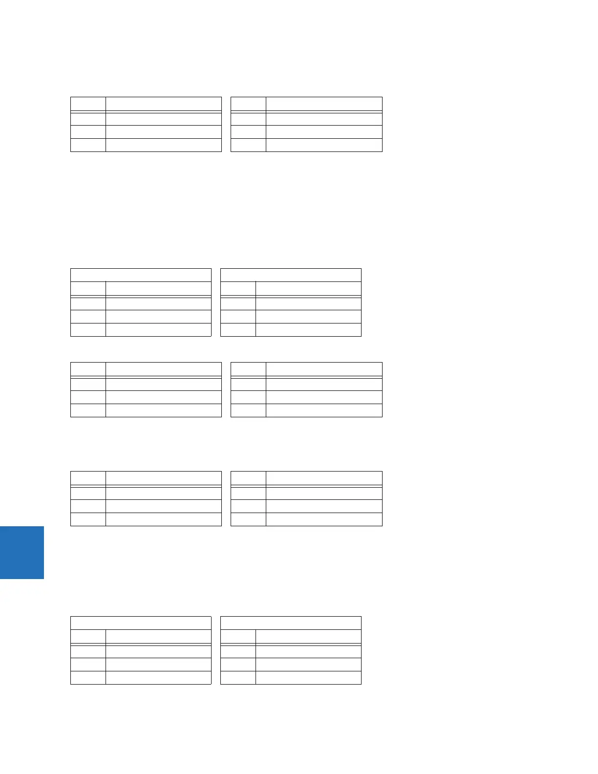
1. Change the current magnitudes as follows.
Phase Differential current (I
d
) Phase Restraint current (I
r
)
A0 ∠0° A 0 ∠0°
B0 ∠0° B 0.801 pu ∠–180°
C0 ∠0° C 0.801 pu ∠0°
Winding 1 Winding 2
Phase Single current (I
1
) Phase Single current (I
2
)
A0 A ∠0° A 0 A ∠0°
B 0.15 A ∠0° B 0.23 A ∠–180°
C 0.15 A ∠–180° C 0.23 A ∠0°
Phase Differential current (I
d
) Phase Restraint current (I
r
)
A0 ∠0° A 0 ∠0°
B 0.044 pu ∠0° B 0.275 pu ∠–180°
C 0.044 pu ∠0° C 0.275 pu ∠0°
Phase Differential current (I
d
) Phase Restraint current (I
r
)
A0 ∠0° A 0 ∠0°
B 0.136 ∠0° B 0.367 pu ∠–180°
C 0.136 ∠0° C 0.367 pu ∠0°
Winding 1 Winding 2
Phase Single current (I
1
) Phase Single current (I
2
)
A0 A ∠0° A 0 A ∠0°
B 0.48 A ∠0° B 1 A ∠–180°
C 0.48 A ∠–180° C 1 A ∠0°
 Loading...


