CHAPTER 8: COMMISSIONING DIFFERENTIAL CHARACTERISTIC TEST EXAMPLES
T35 TRANSFORMER PROTECTION SYSTEM – INSTRUCTION MANUAL 8-7
8
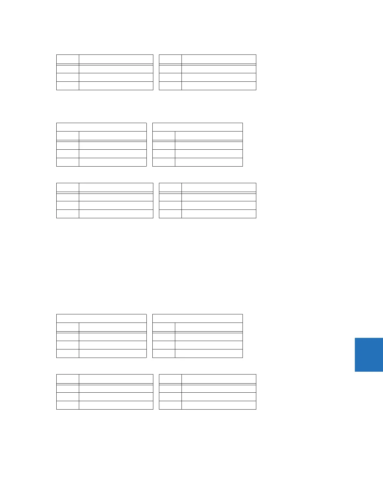
2. Read the following differential and restraint current values from the T35 actual values menu.
The Percent Differential element does not operate even though I
d
is larger than the Minimum Pickup, because I
d
is not
large enough to make the I
d
/I
r
ratio larger than the Slope 1 setting of 15%. The actual ratio is 11.3%.
3. Adjust the I
1
current as follows (thereby increasing I
d
) and verify that the element operates.
4. Read the following differential and restraint current values in the T35 actual values menu.
5. The actual I
d
/I
r
ratio is now 17%. Verify that the element operates correctly.
8.2.2.5 Intermediate curve between Breakpoint 1 and Breakpoint 2
This procedure tests the intermediate section of the differential characteristic curve that lies between the Breakpoint 1 and
Breakpoint 2 points (points B
1
and B
2
on the Differential Restraint Characteristic diagram).
1. Inject currents so that the magnitude of I
r
is between the restraint magnitudes defined by Breakpoint 1 and
Breakpoint 2; that is:
I
r
(at Breakpoint 1) > I
r
< I
r
(at Breakpoint 2) Eq. 8-10
For this example, 2 pu < I
r
< 8 pu. Remember that the maximum current is the restraint current I
r
= 3.5 pu.
2. Read the following differential and restraint current values from the T35 actual values menu.
The I
d
/I
r
ratio is 36.77% and the Differential element does not operate because the actual I
d
= 1.287 pu is still too low
at I
r
= 3.5 pu.
Phase Differential current (I
d
) Phase Restraint current (I
r
)
A0 ∠0° A 0 ∠0°
B 0.113 pu ∠0° B 1 pu ∠–180°
C 0.113 pu ∠0° C 1 pu ∠0°
Winding 1 Winding 2
Phase Single current (I
1
) Phase Single current (I
2
)
A0 A ∠0° A 0 A ∠0°
B 0.45 A ∠0° B 1 A ∠–180°
C 0.45 A ∠–180° C 1 A ∠0°
Phase Differential Current (I
d
) Phase Restraint current (I
r
)
A0 ∠0° A 0 ∠0°
B 0.170 pu ∠0° B 1 pu ∠–180°
C 0.170 pu ∠0° C 1 pu ∠0°
Winding 1 Winding 2
Phase Single current (I
1
) Phase Single current (I
2
)
A0 A ∠0° A 0 A ∠0°
B1.2 A ∠0° B 3.5 A ∠–180°
C1.2 A ∠–180° C 3.5 A ∠0°
Phase Differential current (I
d
) Phase Restraint current (I
r
)
A0 ∠0° A 0 ∠0°
B 1.287 pu ∠–180° B 3.5 pu ∠–180°
C 1.287 pu ∠0° C 3.5 pu ∠0°
 Loading...


