8-8 T35 TRANSFORMER PROTECTION SYSTEM – INSTRUCTION MANUAL
DIFFERENTIAL CHARACTERISTIC TEST EXAMPLES CHAPTER 8: COMMISSIONING
8
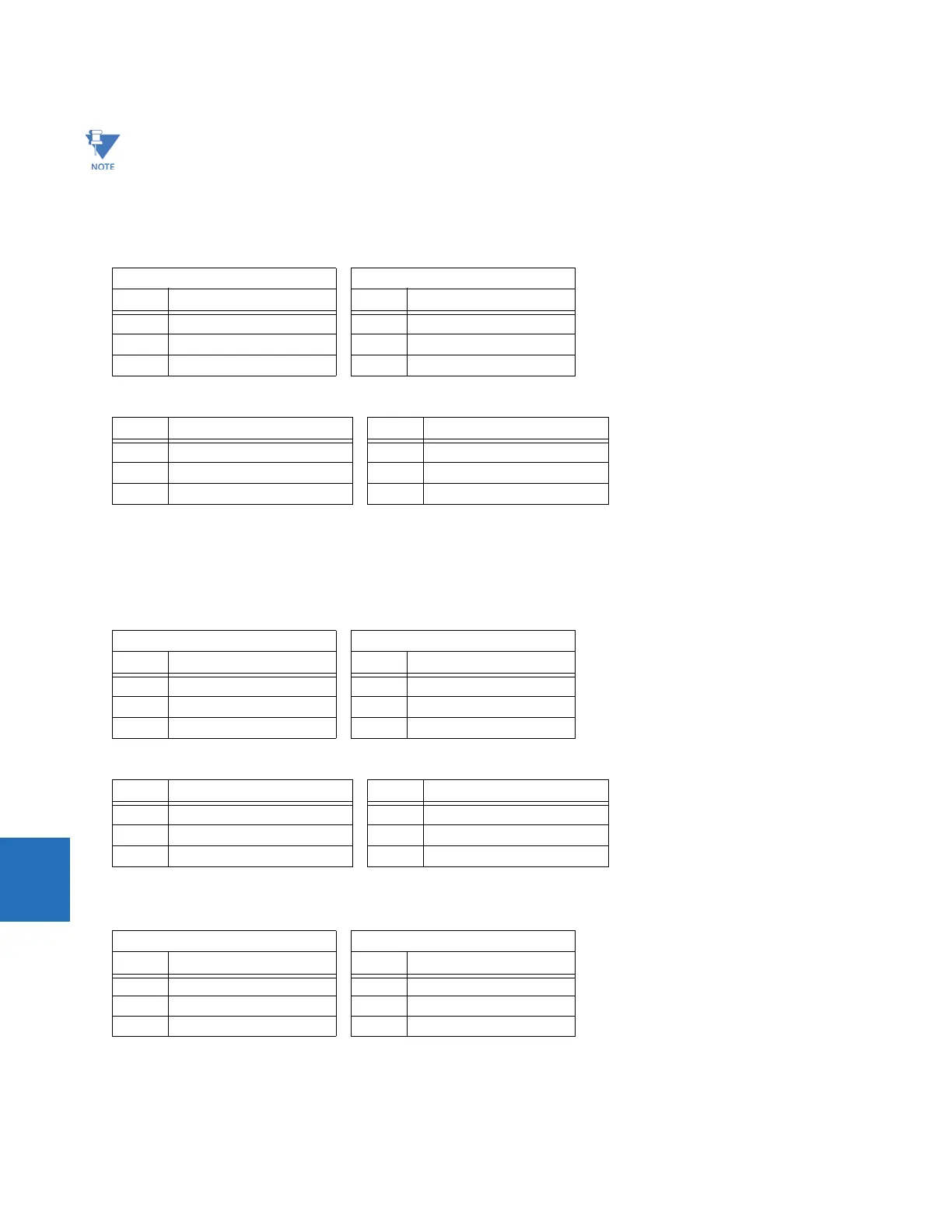
3. In this example, a ratio of I
d
/I
r
> 38% causes the element to trip. Decreasing I
1
as shown in the table increases the
differential current I
d
, causing the element to operate.
4. Read the following differential and restraint current values from the T35 actual values menu.
8.2.2.6 Slope 2 test
Inject currents in such a manner that the magnitude of I
r
is larger than the restraint current at Breakpoint 2; that is,
I
r
> I
r
(Break 2) = 8 pu Eq. 8-11
1. Change the current magnitudes as follows.
2. Read the following differential and restraint current values from the T35 actual values menu.
Since I
d
/I
r
= 89.8% and lower than the required 95%, the Percent Differential element does not operate.
3. Adjust the I
1
current as follows (thereby increasing I
d
) and verify that the relay operates.
Due to the mathematical complexity involved in shaping the curve between Breakpoint 1 and Breakpoint 2, an
Excel-based simulation tool is available from the GE Grid Solutions website (look for the T35/T60 Percent Differential
Element Simulator in the support documents for the product). With this tool, you can see the preset I
d
/I
r
curve point
ratios and the actual I
d
/I
r
ratio as per the entered test currents. The tool graphically indicates differential and
restraint current magnitudes and indicates whether the relay operates.
Winding 1 Winding 2
Phase Single current (I
1
) Phase Single current (I
2
)
A0 A ∠0° A 0 A ∠0°
B1.1 A ∠0° B 3.5 A ∠–180°
C1.1 A ∠–180° C 3.5 A ∠0°
Phase Differential current (I
d
) Phase Restraint current (I
r
)
A0 ∠0° A 0 ∠0°
B 1.471 pu ∠–180° B 3.5 pu ∠–180°
C 1.471 pu ∠0° C 3.5 pu ∠0°
Winding 1 Winding 2
Phase Single current (I
1
) Phase Single current (I
2
)
A0 A ∠0° A 0 A ∠0°
B0.5 A ∠0° B 9 A ∠–180°
C0.5 A ∠–180° C 9 A ∠0°
Phase Differential current (I
d
) Phase Restraint current (I
r
)
A0 ∠0° A 0 ∠0°
B 8.078 pu ∠–180° B 9 pu ∠–180°
C 8.078 pu ∠0° C 9 pu ∠0°
Winding 1 Winding 2
Phase Single current (I
1
) Phase Single current (I
2
)
A0 A ∠0° A 0 A ∠0°
B 0.2 A ∠0° B 9 A ∠–180°
C 0.2 A ∠–180° C 9 A ∠0°