EN-5
Chapter 2 Installation and Wiring
2-1 Installation environment
Observe the following points when installing the inverter.
(1) Install the inverter vertically so that the cable lead-in holes face downward.
(2) Make sure that the ambient temperature is –10°C to 50°C.
(3) Avoid installation in the following environment.
z Place subject to direct sunlight
z Place subject to wind, rain or water
z Place with high levels of humidity
z Place subject to oil drops
z Place where dust, cotton lint or iron chips, etc., are present
z Place with high levels of salt
z Place with harmful corrosive or explosive gases or fluids are present
z Place near sources of vibration such as dollies or press machines
z Place where flammable materials are present
z Place with high levels of
ambient temperature
z Places with high levels of magnetic noise
z Places where radioactive substances are present
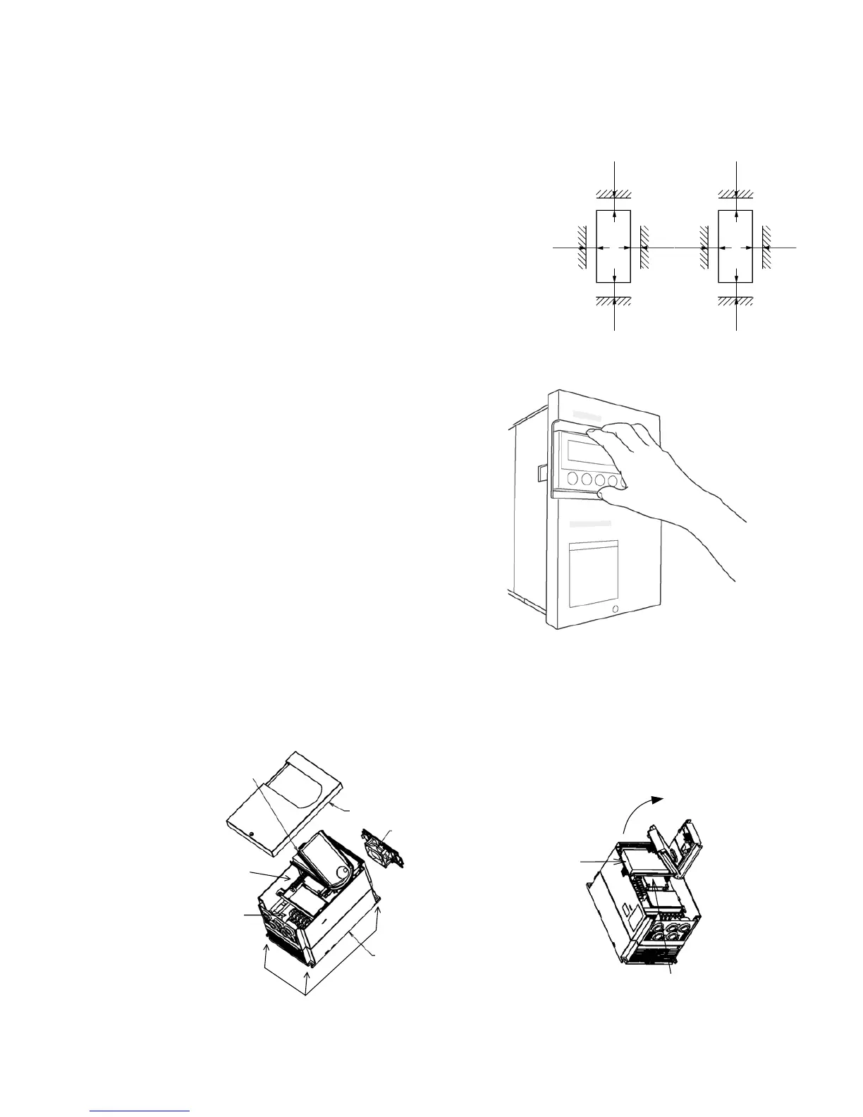
(4) Ensure ventilation space around the inverter. (Refer to Fig. 2-1.)
2-2 Installation and wiring method
Installation and wiring are carried out with the front
cover removed. The operation panel is fixed with the
latches for the operation panel mounting holder, so
the front cover can be removed with the operation
panel attached.
To remove the operation panel, securely hold the
panel with a thumb on the lower side and another
finger on the top side as shown in Fig. 2-2-a, and pull
the panel forward and off. To mount the operation
panel, hold it the top and bottom sides with five
fingers, and press the panel on horizontally. Confirm
that the operation panel is securely fixed with the
latches for the operation panel mounting holder.
Fix the VAT300 at four places when installing. The
lower two installation sections are notched.
The operation panel mounting holder is fixed at the right side and the left side can be raised and
opened as shown in Fig. 2-2-b. In order to make wiring to the control circuit terminal board, remove
the front cover and pull the panel holder forward with slightly pushing its left side to the right direction.
Then the left side of the panel holder will be opened. After closing the panel holder, make sure that the
panel holder is securely fixed to the PCB protection case.
Cooling fan
Main body case
Front cover
Operation panel
and mounting holder
Pull the panel holder forward
with slightly pushing its left side
to the right direction.
The left side can be opened.
Fig.2-2-b
Unit installation hole
(Totals four places)
Main circuit
terminal block
Control circuit
terminal block
PCB protection case
Fi

 Loading...


