GE_UPS_OPM_VHU_0K7_3K0_XUS_V011.docx Operating Manual VH700 UL, VH1000 UL, VH1500 UL, VH2000 UL & VH3000 UL
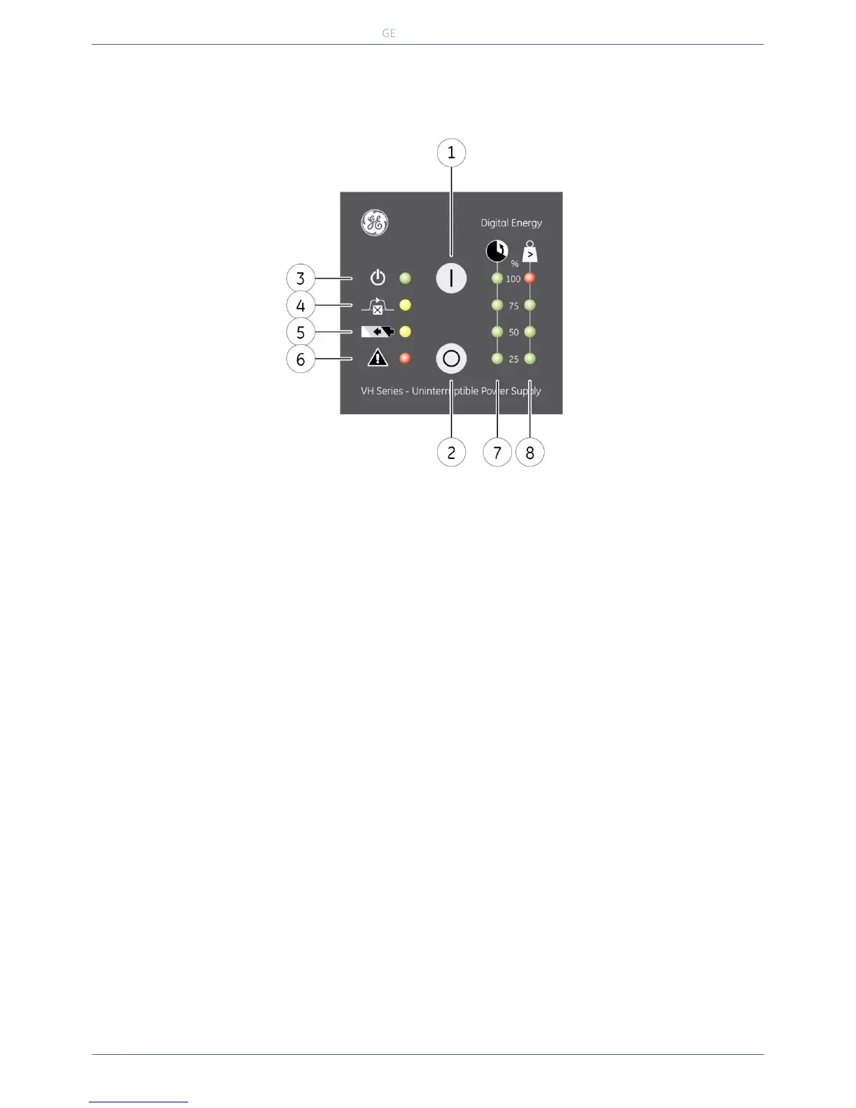
switch / LED main function
1 - ‘on’ switch switches on the UPS, starts quick battery test (see 4.6)
2 - ‘off’ switch switches off the UPS
3 - LED ‘operation’ on when the UPS is operating
blinks if the UPS is in standby mode
4 - LED ‘on bypass’ on when the UPS operates in bypass mode: the incoming mains power is channeled
directly to the load
5 - LED ‘on battery’ on in case of battery operation: the mains power fails, and the internal batteries
supply the required power until either they are depleted or mains power returns.
6 - LED ‘alarm’ blinks in case of an alarm
7 - LED bar ‘runtime capacity’ the remaining available battery runtime for the actual load, in % of the maximum
runtime with the actual load
8 - LED bar ‘load’ indicates to what extent the output capacity of the UPS is used by the actual load. If
e.g. the 25% and 50% LED are on, the load exceeds 50% of the maximum load. If all
4 LEDs are on the unit operates in overload. As this is an abnormal situation the
alarm LED will blink as well.
More info in section 4.3.2 and 4.4.8.
 Loading...