GE MEDICAL SYSTEMS
D
IRECTION 2300164-100, REVISION 7 VIVID™ 3 PRO/VIVID™ 3 SERVICE MANUAL
Chapter 7 - Diagnostics/Troubleshooting 7-27
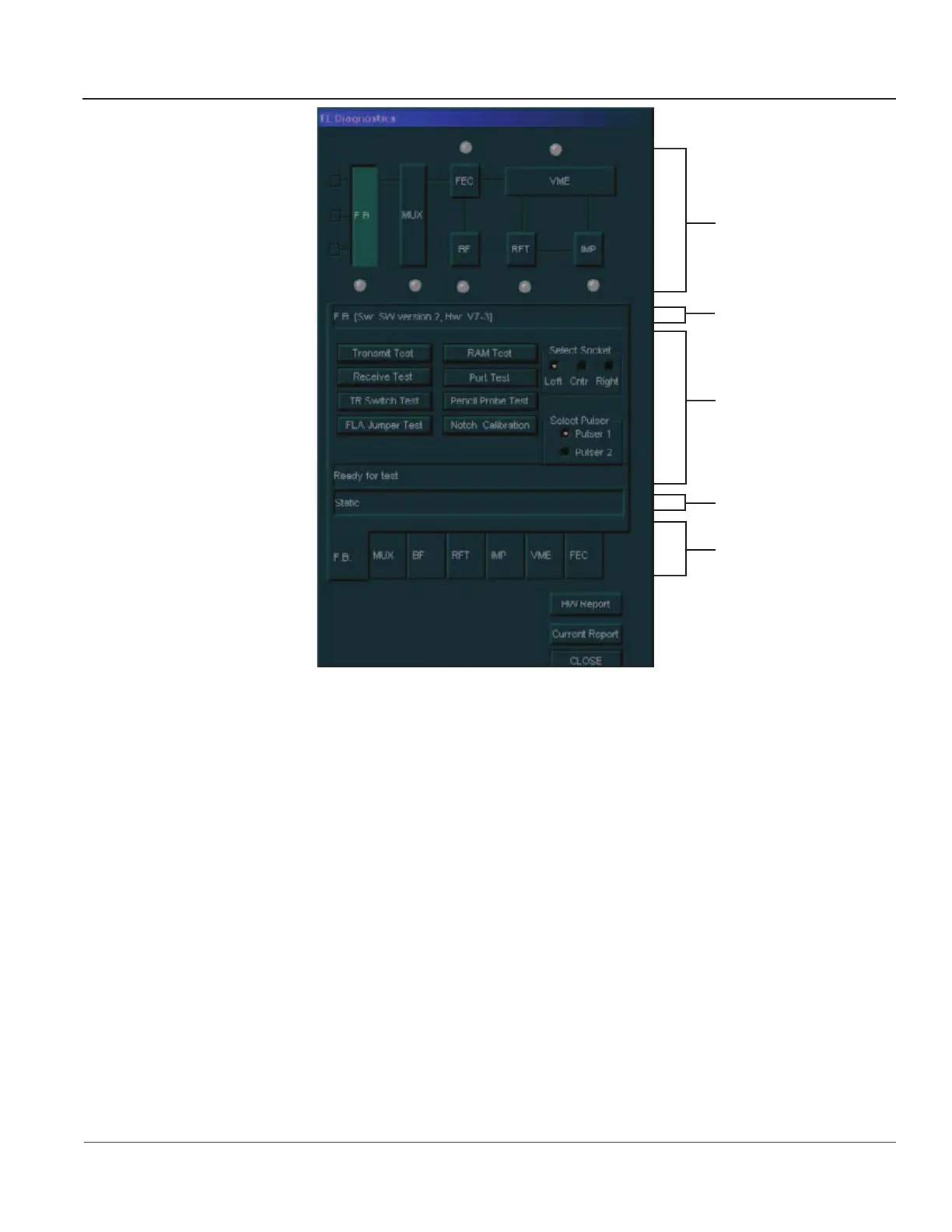
Figure 7-15 F.B. Tab - FE Diagnostics Dialog Box (RFT Configuration)
3) Trackball to the following buttons (in the order shown) and press Select:
a.) Transmit Test: Checks the FE pulsers via the probe elements, as described in theTransmit
Test
section, on page 7-28.
b.) Receive Test: Tests each amplifier output against the predefined output level, as described
in the
Receive Test section, on page 7-34.
c.) TR Switch Test: Checks the transmit switches, as described in the TR Switch Test section,
on page 7-38.
d.) FLA Jumper Test: Checks the jumpers that connect the side elements to the center elements,
as described in the
FLA Jumper Switch section, on page 7-30.
e.) Pencil Probe Test: Checks the transmitting channels associated relays to the pencil probe
port, as described in the
Pencil Probe Test section, on page 7-40.
f.) Port Test: Checks general logic control and ports logic, as described in Port Test section, on
page 7-44.
g.) RAM Test: Checks the RAM that stores the delays for the transmitted ultrasound signals to
the form focal beam, as described in the
RAM Test section, on page 7-45.
Data Flow Map
Test Description Area
Test Area
Comment Area
Tabs
Artisan Technology Group - Quality Instrumentation ... Guaranteed | (888) 88-SOURCE | www.artisantg.com
 Loading...


