GE MEDICAL SYSTEMS
D
IRECTION 2300164-100, REVISION 7 VIVID™ 3 PRO/VIVID™ 3 SERVICE MANUAL
7-30 Section 7-3 - Performing Front End (FE) Diagnostics
7-3-8-3 FLA Jumper Switch
All the elements are connected through the transmit and receive jumpers. This test checks the jumpers
that connect the side elements to the center elements. During this test, every probe element transmits
and receives signals. The test has two phases, namely Open jumper test and Closed jumper test.
1) Connect the 10L (739L) probe and lock it in place.
Note: To avoid irrelevant failure results, it is imperative that only this probe is used and
that it be in good condition.
2) Access the F.B. tab of the FE Diagnostics dialog box, as described in the
Accessing the Front Board
Assembly Options
section, on page 7-25.
3) In the Select Socket area of the F.B. tab, trackball to the socket to which the 10L probe is connected:
• Trackball to Left, Right or Center and press Select.
4) Trackball to Pulser 1 (High Voltage Power Supply [HVPS] +/-80V) or Pulser 2 (Low Voltage Power
Supply [LVPS] +/-40V) and press Select.
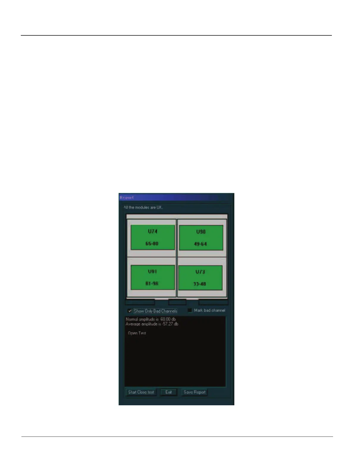
5) Trackball to the FLA Jumper Test button and press Select. The open FLA jumper test is
performed, and the test results are displayed in the Report dialog box, as shown below:
Figure 7-17 Report Dialog Box - Open FLA Jumper Test
Artisan Technology Group - Quality Instrumentation ... Guaranteed | (888) 88-SOURCE | www.artisantg.com
 Loading...


