GE MEDICAL SYSTEMS
D
IRECTION 2300164-100, REVISION 7 VIVID™ 3 PRO/VIVID™ 3 SERVICE MANUAL
3-16 Section 3-4 - Preparing for Installation
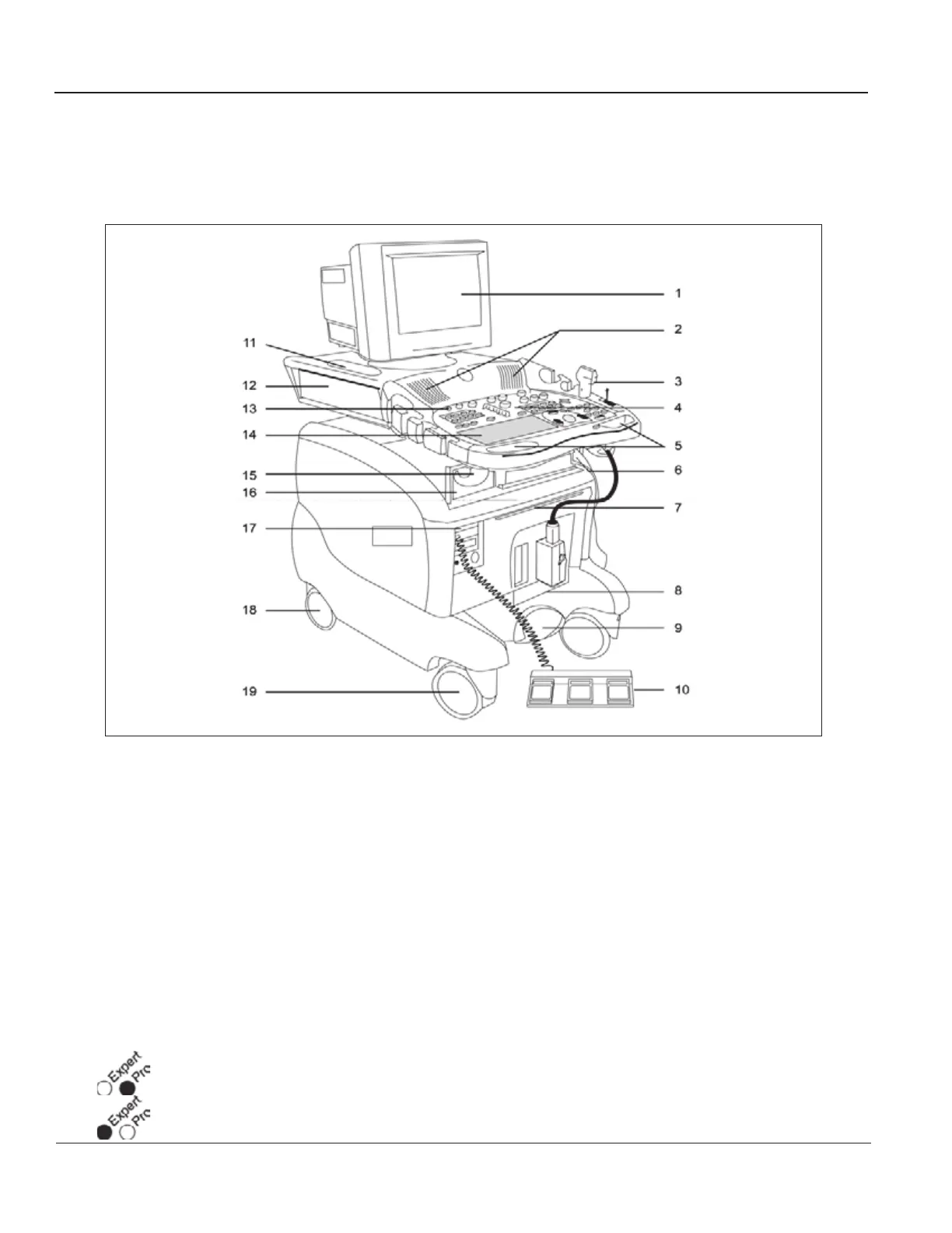
3-4-3-2 Front and Side View of the Vivid™ 3 Ultrasound Unit
Figure 3-11 below shows the Vivid™ 3 ultrasound unit components that are visible from the front and
side of the ultrasound unit.
1 Display Monitor: Swivels to the left and right, and tilts up and down.
2 Speakers: Two loudspeakers for Doppler sound.
3 Probe Holders and Probes: Situated on either side of the front panel.
4 Control Panel: Contains the alphanumeric keyboard and the buttons used to operate the ultrasound
unit.
5 Front Handle.
6 Raise/Lower the Control Console Up/Down Handle: Located midway underneath the front handle.
Used to raise or lower the control console (control panel and monitor).
7 Air Filter: Located above the crate.
8 Probe Ports:
• Three active probe connectors (one for a pencil probe), and a fourth, inactive port on the right
side of the unit, which is used for parking.
• Four active probe connectors (one for a pencil probe).
Figure 3-11 Front and Side View of the Vivid™ 3
Left
Right
Artisan Technology Group - Quality Instrumentation ... Guaranteed | (888) 88-SOURCE | www.artisantg.com