GE MEDICAL SYSTEMS
D
IRECTION 2300164-100, REVISION 7 VIVID™ 3 PRO/VIVID™ 3 SERVICE MANUAL
Chapter 3 - Installation 3-25
3-5-2-1-2 Left Rear Panel Connectors
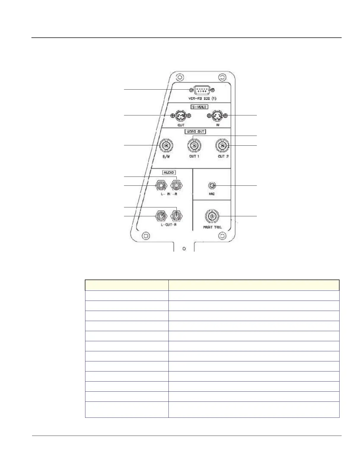
Table 3-10 describes the connectors included in the left rear panel (shown in Figure 3-16):
Figure 3-16 Left Rear Panel Connectors
Table 3-10 Left Rear Panel Connectors
Name Description
1. VCR-RS 232 (1) One standard 9-pin RS232 (1) connector for VCR control (COM 1).
2. S-VIDEO OUT Y/C Video Out: 4 pin connector for output to an S-VHS VCR.
3. S-VIDEO IN Y/C Video In: 4 pin connector for input from an S-VHS VCR.
4. VIDEO OUT B/W BNC connector for composite B/W video output to a hard copy printer.
5. VIDEO OUT 1 BNC connector for composite color video output (PAL or NTSC).
6. VIDEO OUT 2 BNC connector for composite color video output (PAL or NTSC).
7. AUDIO IN (RIGHT) RCA jack.
8. AUDIO IN (LEFT) RCA jack.
9. AUDIO OUT (RIGHT) RCA jack.
10. AUDIO OUT (LEFT) RCA jack.
11. MIC Microphone input.
12. PRINT TRIG.
BNC connector for the exposure control of a multi-imager or another peripheral
activated by pressing Print B.
1
2
4
6
7
10
12
3
8
5
9
11
Artisan Technology Group - Quality Instrumentation ... Guaranteed | (888) 88-SOURCE | www.artisantg.com
 Loading...


