GE MEDICAL SYSTEMS
D
IRECTION 2300164-100, REVISION 7 VIVID™ 3 PRO/VIVID™ 3 SERVICE MANUAL
Chapter 3 - Installation 3-27
Note: All the color printer cables are located in the left storage compartment under the metal cover.
3) After connecting the remaining peripherals and switching the system ON, configure the printer
settings, as described in the Printers Tab section, on page 3-43.
For more details about peripherals installation, refer to the Vivid™ 3 Peripherals Installation Manual.
3-5-2-5 Connecting the DeskJet Color Printer HP6122
Note: If there is sufficient space, the DeskJet Color Printer may be installed under the control
console. Alternatively, it will require a suitable stand or table to be positioned in close
proximity to the Vivid™ 3 scanner - at a distance of not more than 1m (3.3 ft) from the power
connection to the Vivid™ 3 unit.
WARNING: Whenever moving the Vivid™ 3 scanner, the DeskJet Color Printer must be
disconnected from the scanner. DO NOT attempt to move the two units simultaneously without
first disconnecting them. After relocation, re-connect the printer to the scanner.
1) Place the DeskJet color printer on the shelf below the control console (or alternatively on the
designated stand or table, adjacent to the unit).
2) Connect the following cables as shown in
Table 3-14:
3) After connecting the remaining peripherals and switching the system ON, configure the printer
settings, as described in the Printers Tab section, on page 3-43.
For more details about peripherals installation refer to the Vivid™ 3 Peripherals Installation Manual.
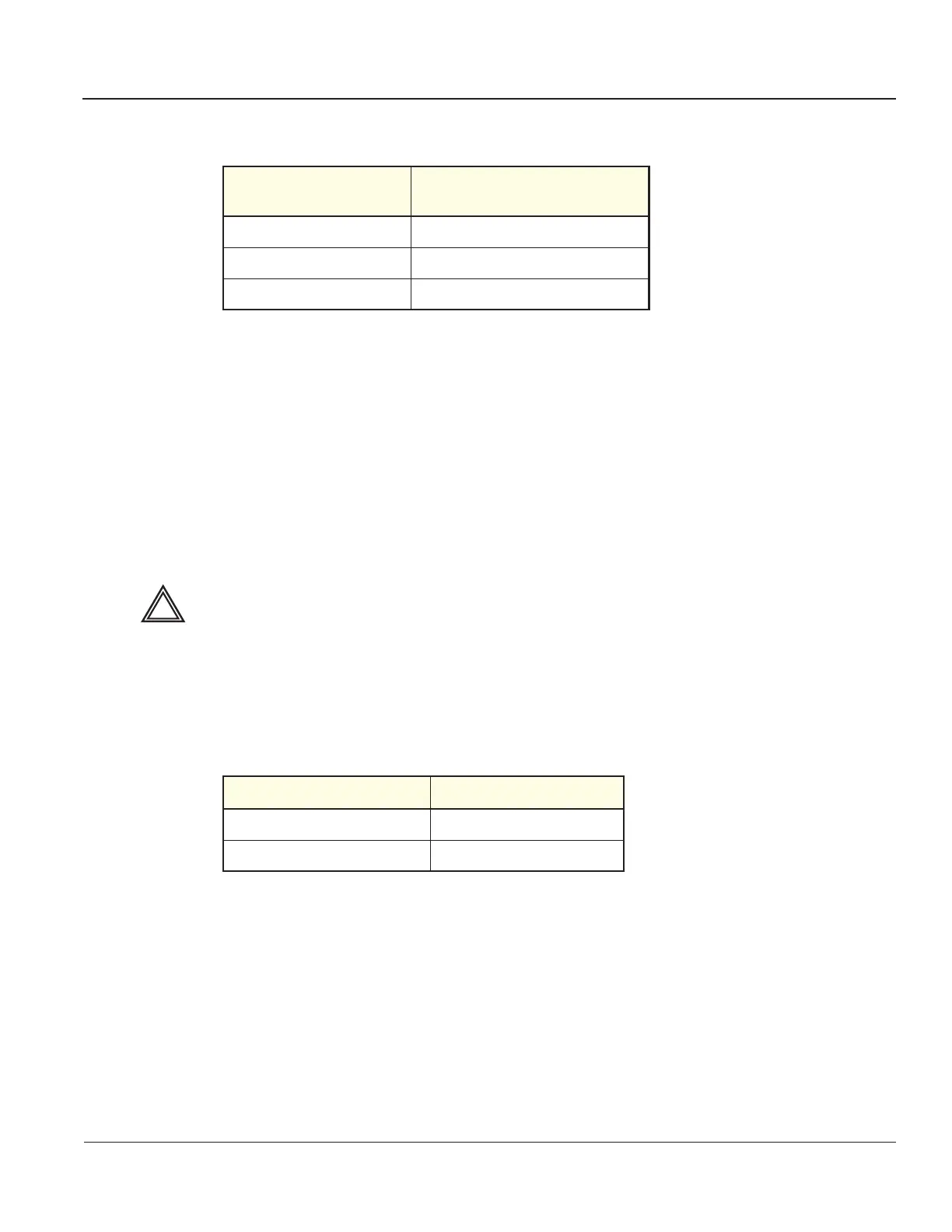
Table 3-13 Color Printer Cables
From the Color Printer
To the Cables
underneath the Control Console
Video IN Composite/Video OUT 1
External Trigger Print Trigger
AC IN AC Power Cable
Table 3-14 DeskJet Color Printer Cables
From the Color Printer To the Right Panel
Parallel Port Connector Parallel Port
AC IN (AC Dual Power cable) Panel AC outlet
Artisan Technology Group - Quality Instrumentation ... Guaranteed | (888) 88-SOURCE | www.artisantg.com