– 28 –
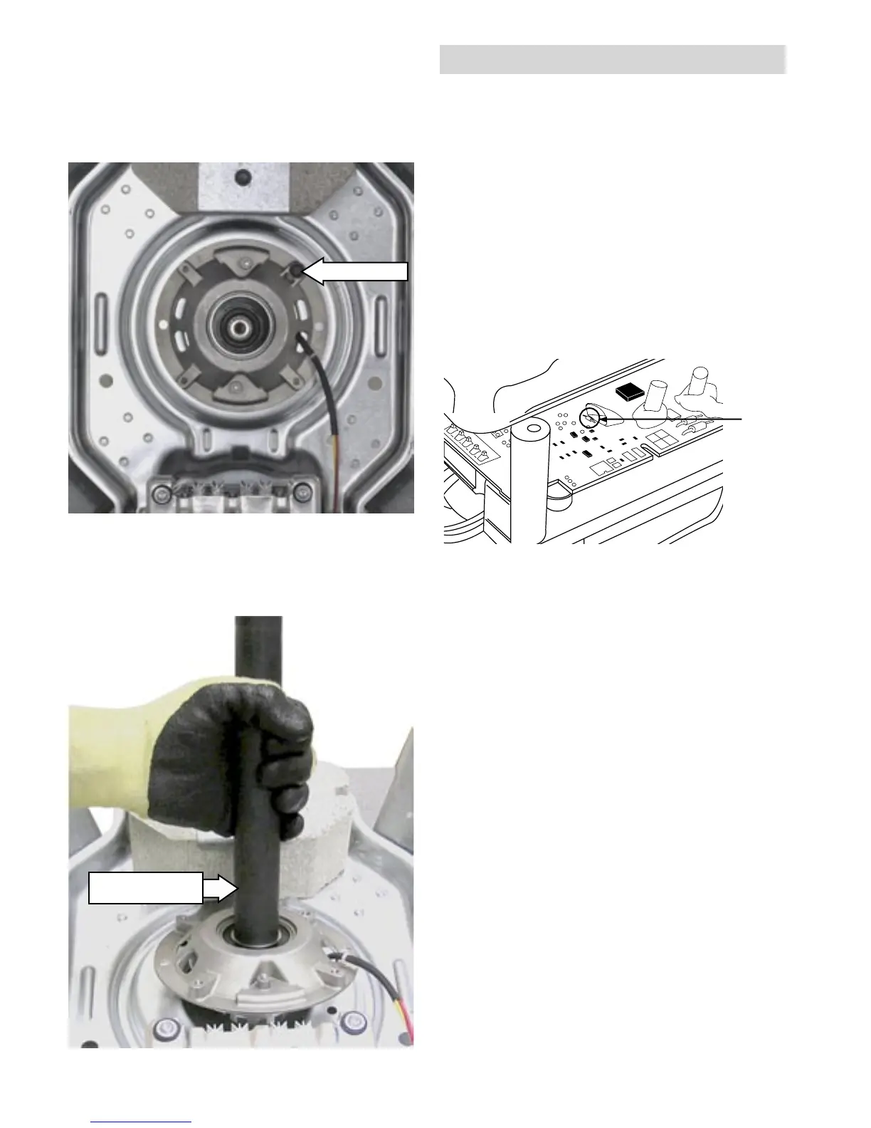
Lift the shaft and mode shifter assembly from
the platform.
13.
Shaft and Mode
Shifter Assembly
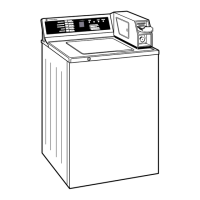
Remove the inverted single 3/8" hex-head bolt
from the top of the platform.
Note: Torque the four 3/8" hex-head bolts to 90 in.
lbs. when reinstalling.
12.
Inverted Bolt
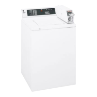
Inverter/Motor Signal LED
• An LED beneath the inverter cover can be viewed
for diagnostic testing. (It is best viewed from the
right side of the motor.)
• When Motor is operating normally, and running,
the LED blinks at a constant rate of 1/2 second
on and 1/2 second off.
• When Motor is operating normally, and idle, the
LED blinks at a constant rate of 1 second on and
1 second off.
• Motor/control error condition – LED is on for .25
seconds and off for .25 seconds for a specified
number of times, during a 6-second period. The
6-second cycle repeats continuously.
(Continued next page)
 Loading...