Do you have a question about the GE WPRE6100 and is the answer not in the manual?
Explains the process of agitation mode engagement and motor speed control.
Details the sequence for engaging spin mode and ensuring proper cam engagement.
Adjusts water level based on load size for optimal cleaning.
Selects wash and rinse water temperatures, with PerfecTemp option.
Features like Autosoak, 2nd Rinse, and Extended Spin for enhanced washing.
Shows approximate time left in the cycle, dynamically adjusting for fill time.
Controls the length and intensity of the washing process based on fabric type.
Initiates, pauses, and cancels cycles; requires pressing for 3 seconds to stop.
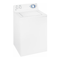
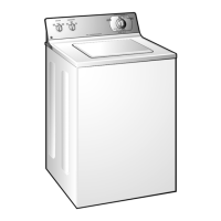
Identifies key components visible from the front of the washer.
Shows components accessible when the control panel is in service position.
Details on shipping rod location and leveling leg adjustments for stability.
Instructions for removing and correctly aligning the dual-action agitator.
Steps to remove the control panel to access internal components.
Information on main and secondary boards, connections, and knob removal.
Step-by-step guide to remove the water level switch and its components.
Instructions for disconnecting and removing the dual solenoid water valve.
Notes on the filter's purpose, access, and grounding for noise reduction.
Explains the safety feature and how to access/release the lid switch.
Steps to detach the front panel for access to internal components.
Instructions for removing the top cover/lid assembly from the washer.
Guide to removing and testing the ATC thermistor for temperature regulation.
Steps to remove the drain pump, noting residual water.
Steps for replacing the drive belt using a specialized tool.
Detailed steps for removing the inverter/motor assembly, including safety precautions.
Explains the four rod/spring assemblies that suspend the tub and motor.
Instructions for removing the tub cover by releasing dampening straps and tabs.
Steps to remove the entire tub assembly, including related components.
Steps for removing the shaft and mode shifter assembly after tub removal.
Chart detailing cycle times with various options for different wash programs.
Procedure to enter diagnostic mode for testing components and accessing errors.
Explains how to read the chart and interpret LED active modes and functions.
Details knob positions, component activation, and error code descriptions.
Steps to safely exit the diagnostic mode and return to normal operation.
Identifies LED patterns on the inverter for basic diagnostic testing.
Detailed descriptions of error codes based on LED flash counts and patterns.
Specifies voltage checks at harness plugs for inverter/motor diagnostics.
Procedure to test the mode shifter coil's continuity and resistance.
How to perform the brake test and interpret results for component failure.
Provides a wiring diagram and color code key for troubleshooting.
Outlines the warranty period for parts and associated labor costs.
Lists conditions and damages not covered by the product warranty.
| Brand | GE |
|---|---|
| Model | WPRE6100 |
| Capacity | 3.5 cu. ft. |
| Color | White |
| Energy Star Certified | No |
| Delay Start | Yes |
| Steam Option | No |
| Vibration Reduction Technology | No |
| Washer Type | Top Load Washer |