– 29 –
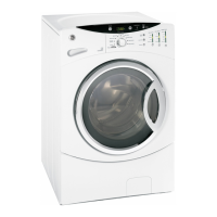
Inverter / Motor Test
Voltage readings:
C2 Pin 1 = Gnd
C2 Pin 3 = N
C2 Pin 5 to Pin 3 = 120 VAC
C2 Pin 6 to Pin 3 = 120 VAC with lid switch closed
C7 Pin 1 to Pin 2 = 135 VDC**
C7 Pin 1 to Pin 2 = 30 VDC**
** 135 VDC is present for approximately 15 seconds
at the beginning of the agitate program. 30 VDC is
present during the remainder of the agitate cycle.
Note: All electrical testing is done at harness plug.
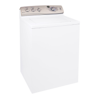
Mode Shifter Coil Test
Note: The mode shift coil connects to C7
connector on inverter/motor assembly. Unplug C7
connector and check continuity. Mode shift coil
resistance value is approximately 98Ω @ room
temperature (77° F).
 Loading...