Do you have a question about the GEA Ariete NS3015P and is the answer not in the manual?
Provides detailed technical data, specifications, and parameters for the machine.
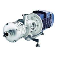
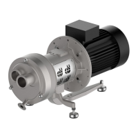
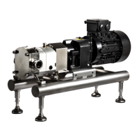
Offers a general overview of the GEA Niro Soavi pump's construction and function.
Explains the fundamental operating principle of the pump through a diagram.
Specifies the machine's type as a PUMP.
Indicates the specific model of the machine, NS3011P.
Provides the unique serial number for the machine, 13490.
Shows the date associated with the technical datasheet, 07/12/17.
States the maximum working pressure the machine can handle, 250 bar.
States the maximum product temperature the machine can handle, 90 °C.
Indicates the diameter of the plungers, 35 mm.
Defines the setpoint for the overpressure valve, 300.
Specifies the type of connection for the inlet, DN25 DIN11851.
Details the type of connection for the outlet, FLANGE 1/2" SCH.40S (AISI 316L).
States the power of the main motor, 15.0 (20HP) kW.
Specifies the main voltage supply, 460 V.
Indicates the main frequency supply, 60 Hz.
Provides a legend for various instrument symbols used in diagrams.
Explains the meaning of different types of process lines shown in diagrams.
Provides a legend for various machinery and equipment symbols.
Details the sound pressure level of the machine, measured in dB(A).
Lists recommended brands and types of lubricating oils for the machine.
Specifies the oil capacity of the lubrication plant for different machine models.
Provides guidelines and warnings to ensure safe operation and prevent accidents.
Explains the design, function, and advantages of the overpressure valve for machine protection.
Specifies what is covered by the guarantee and the conditions under which it is void.
States the duration of the guarantee period, typically 12 months from delivery.
Offers specific recommendations for storing the machine before installation, including temperature and humidity.
Details how to position the machine correctly for operation, maintenance, and safety.
Provides general information about the GEA Niro Soavi high-pressure piston pumps.
Specifies the recommended operator position during start-up and adjustment operations.
Explains how to use the emergency stop function to halt the machine instantly in hazardous situations.
Explains the function and operation of the overpressure valve designed to protect the machine.
Provides general information and guidelines for performing maintenance operations.
Details the procedures for routine and scheduled ordinary maintenance tasks.
Explains how to effectively use the spare parts catalogue to identify and order components.
Details the procedure for ordering spare parts, including necessary information to provide.
Lists essential spare parts recommended to be stocked to minimize downtime and ensure availability.
Provides access to wiring diagrams for electrical devices and the electric power board.
Lists suppliers' catalogues and components installed in the machine, with specific instructions for any installed components.
Lists the part code and description for the MOTOR.
Lists the part code and description for the MOTOR.
Lists the part code and description for the TRANSDUCER.
Lists the part code and description for the TRANSDUCER.
Lists the part code and description for the GEARBOX.
Lists the part code and description for the LUBRICATION UNIT.
| Brand | GEA |
|---|---|
| Model | Ariete NS3015P |
| Category | Water Pump |
| Language | English |