A
A
a
a
A
A
a
a
4| Compressor assembly
4.1 Setting up
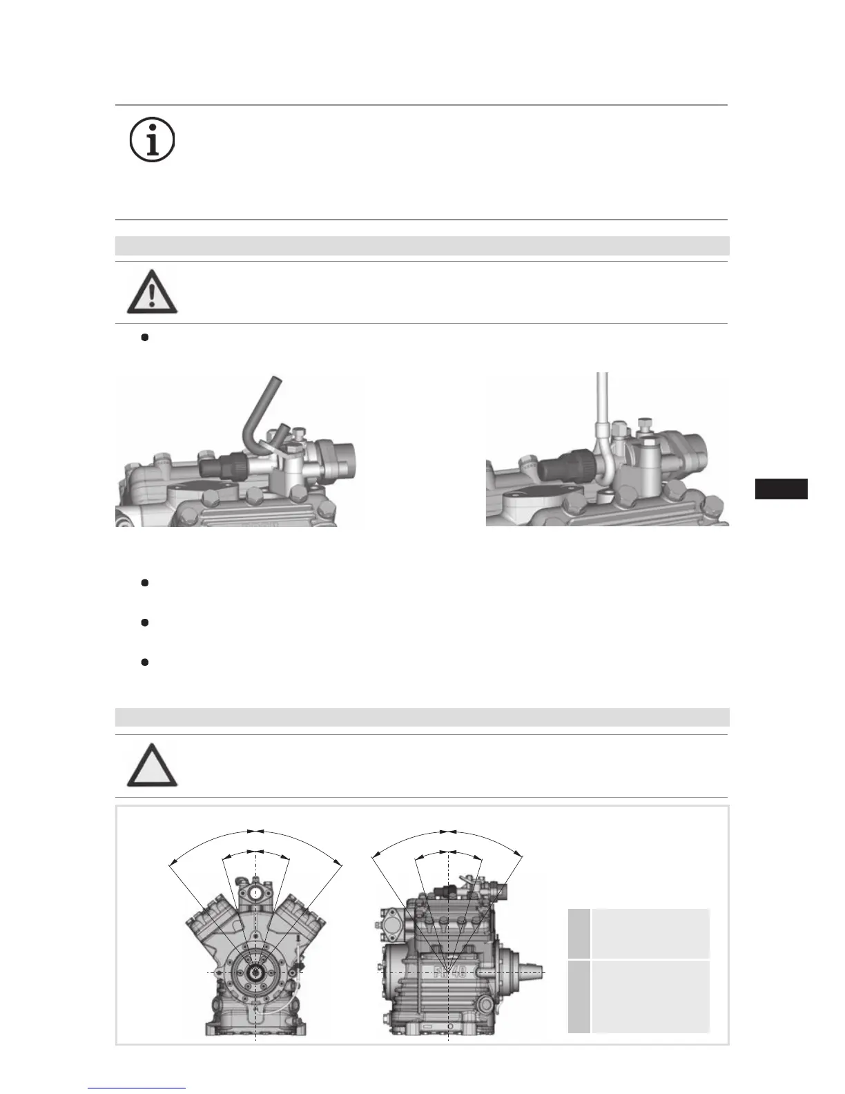
4.2 Maximum permissible inclination
A
max. 30°,
max. 2 minutes
a
max. 15°,
continuous
operation
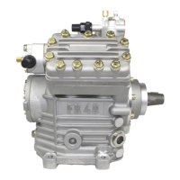
Fig. 8
Fig. 9
Transportandsuspensionunitontheeyebolt(Fig.8)ordirectonthedischargelinevalve
(Fig.9).
Fittings (e.g. pipe holders, additional units etc.) on the compressor are permissible only
following consultation with GEA.
Setuponanevensurfaceorframewithsufcientload-bearingcapacity.Useall4fastening
points.
Correct setup of the compressor and mounting of the belt drive are decisive for running comfort,
operating safety and the service life of the compressor.
Fig. 10
INFO Newcompressorsarefactory-lledwithinertgas(3barnitrogen).
Leave this service charge in the compressor for as long as possible
and prevent the ingress of air.
Check the compressor for transport damage before starting any
work.
ATTENTION Poor lubrication can damage the compressor. Respect the stated
values.
WARNING Movecompressorsonlywithhoiststhathaveadequateload-bear-
ing capacity.
 Loading...