OPERATING INSTRUCTIONS
CO
2
/NH
3
CASCADE UNIT
250 - 1000 KW
_551511_om_kas_gbr_1_.doc 35
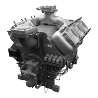
fig. 26: Diagram of the main components of the CO
2
/NH cascade, Part 2
3
These cascade units are delivered completely assembled, so that on site only the following have to be integrated:
— the CO
liquid line to the CO evaporators / freezing apparatus (not included in scope of supply)
2 2
— the return line to the CO
2
liquid separator
— the heat transfer medium lines of the NH
compressor
3
— Compressor discharge gas (hot gas) and liquid lines to the NH
3
condenser on site
— the vent pipes of the CO
and NH safety valves,
2 3
In the case of cascades, which due to their size cannot be transported as a complete unit, the liquid separator is
dismantled in the factory. This has to be re-installed on site and connected to the relevant refrigerant lines.
3.2 Refrigerant circuit
3.2.1 CO
2
low temperature stage
The compressors of the low temperature stage are
state of the art screw compressors, specially
developed for the CO
2
refrigerant from the Grasso
series C (see compressor manual, drawings and parts
list).
The CO
2
screw compressor sucks in the refrigerant
vapour from the CO
2
liquid separator via the suction
filter.
After the CO
2
refrigerant has been compressed to
condensing pressure the condensing takes place in
the plate pack of the cascade heat exchanger by
extracting the heat generated by the evaporation of
NH
3
in the shell-side.
The liquid CO
2
in the liquid separator is expanded
(relaxed) with the help of an electronic injection
valve in conjunction with an electronic high-pressure
level controller
In the liquid separator, the refrigerant vapour and
liquid are separated. The CO
2
liquid is passed
through the system's evaporator (not included in the
scope of supply) by means of hermetic refrigerant
pumps (pump circulation principle).
Here heat is absorbed in order to cool the medium
to be cooled.
 Loading...