OPERATING INSTRUCTIONS
CO
2
/NH
3
CASCADE UNIT
250 - 1000 KW
36 _551511_om_kas_gbr_1_.doc
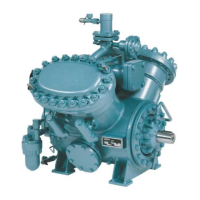
The refrigerant pumps can be individually shut off
and are protected against dirt by generously
dimensioned filters in the inlet.
The oil carried through the pressure line and the
condenser into the liquid separator while the
compressor is running is directly injected back into
the compressor with the help of partial flow
deoiling.
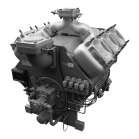
3.2.2 NH
3
high temperature stage
The NH
3
circuit includes a complete chiller unit and
its design corresponds to the FX VP type series,
whereby the evaporator is installed as a cascade
evaporator condenser. The condenser already exists
on site.
The NH
3
compressors of the high temperature stage
are modern, highly efficient screw compressors of
the LT series (see compressor's manual, drawings and
parts list).
The NH
3
screw compressor sucks in the refrigerant
vapour from the NH
3
liquid separator of the cascade
evaporator via the suction filter.
After the NH
3
refrigerant has been compressed to
condensing pressure it is condensed in the condenser
(Grasso scope of supply or installed on site).
The liquid NH
3
in the liquid separator of the cascade
evaporator is expanded (relaxed) with the help of an
electronic injection valve in conjunction with an
electronic high-pressure level controller.
In the liquid separator, the refrigerant vapour and
liquid are separated. From there the liquid
refrigerant is passed via an outer circulation pipe
into the shell-side of the cascade evaporator.
The quantity of heat absorbed during evaporation of
the NH
3
coolant is drawn from the CO
2
refrigerant
gas flowing in the heat exchanger plates.
The NH
3
coolant therefore evaporates in the shell-
side, while CO
2
condenses in the plates.
The oil carried via the pressure line and the
condenser into the liquid separator while the
compressor is running is separated from the
refrigerant again with the help of cyclically operated
automatic oil return and is passed back to the
compressor.
This is a basic precondition for a fault-free operation
of the evaporator system.
3.3 Oil return system
The refrigerant cycles have an automatic oil return
system with which the oil accumulated in the
compressor's oil sump is cyclically returned to the
intake side of the compressor.
3.3.1 CO
2
circuit oil return system
Despite the very low oil carry over of the screw
compressor, over a longer period soluble refrigerator
oil accumulates in the liquid CO
2
on the low pressure
side.
The result of this is the oil level in the oil separator
falls during the startup period and oil has to be
added accordingly.
A slight accumulation of oil in the refrigerant does
not have any negative effects on the system side and
is completely normal.
To limit this accumulation of oil, the oil is returned
with the help of partial flow deoiling on the
discharge side of the CO
2
pumps.
The partial flow is directly injected into compressor.
3.3.2 NH
3
circuit oil return system
The NH
3
side oil return system already tried and
tested in the Grasso chiller series is cyclically carried
out in the following steps:
1. Filling the Draining Tank (2300)
The oil carried from the compressor in the
refrigerant circuit is fed into the deoiling vessel
at the evaporator's "oil dome".
At the same time, the solenoid valve (2305) is
opened. The solenoid valve (2310) is closed.
The oil accumulating in the evaporator's oil
dome continuously runs into the deoiling vessel.
2. Evaporation of refrigerant
Any liquid refrigerant in the deoiling vessel can
evaporate by adding ambient heat. At the same
time, oil runs in and the oil level in the vessel
rises.
After a fixed unit of time the oil is then pushed
out of the deoiling vessel.
After the evaporation process a solenoid valve
(2310) is briefly opened and hot gas presses the
oil out of the deoiling vessel back into the
compressor's intake side.
The control timed for the solenoid valve can be
parameterised at the control.
3.4 Auxiliary refrigeration unit for CO
2
separator
The maximum operating pressure of the low
pressure side of the CO
2
circuit is 25 bar g.p. The
section of the circuit is equipped with a discharging
safety valve.

 Loading...