OPERATING INSTRUCTIONS
CO
2
/NH
3
CASCADE UNIT
250 - 1000 KW
_551511_om_kas_gbr_1_.doc 49
• the type of heat carrier or cooling agent circuit
(open or closed),
• the quality of the heat carrier or cooling agent,
• the materials in the circuit,
• the flow rate.
Deposits on the tubing of the heating exchangers
increase the difference in temperature between the
condenser temperature (t
C
) and heat-carrier outlet
(t
) or between evaporating temperature (t
W2 0
) and
cooling agent outlet (t
K2
) lead to greater pressure
drops. This reduces the chiller’s performance, output,
flow rates, etc. The pump power input is increased.
The cleaning cycle depends on the installation and
should be defined in accordance with it.
4.6.14.1 Chemical cleaning
A specialized company has to perform the chemical
cleaning of the equipment. The materials used in the
components of the package must be taken into
account in this respect.
Chemical cleaning requires a separate cleaning circuit
for which separate connection possibilities should be
provided. To do so, proceed as follows:
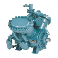
fig. 27: Oil fine separation cartridge
• Block the corresponding heat exchanger from
the remaining circuit
4.6.13 Finding and fixing leaks
Lower refrigerant levels in the containers are due to
loss of refrigerant as a result of leaks. For this reason,
all pipes, connections and valve glands should be
checked regularly, especially in the initial period after
fitting, with a suitable indicator (litmus paper, etc.).
• Drain the heat carrier/cooling agent or cooling
water from the heat exchanger
• Connect the cleaning circuit to the heat
exchanger (check for leaks into the environment
and other parts of the circuit and remedy if
necessary).
Leaks are revealed by a change of colour and must
be sealed immediately.
The handling and cleaning technology must
conform to the manufacturer’s information
pertaining to the cleanser (neutralization,
flushing, disposal).
The supplier is not liable for losses of refrigerant
caused by a lack of or improper maintenance!
New flange gaskets made of It-KVD are subject to
fatigue immediately after installation. For this reason
the flange screws should be tightened three times at
24-hour intervals. After that, hardly any further
fatigue will be observed.
The delivery rate of the pump for the cleaning
circuit has to be set in such a way that dislodged
contaminants and particles do not cause the
heat exchanger to become clogged. The cleaning
circuit must be in the form of an open circuit to
prevent pressure from building up in the system
and to be able to observe the cleaning process.
4.6.14 Cleaning the heat exchangers (heat-carrier
/ cooling agent sides)
To avoid excessive soiling, the unit has to be
equipped with a filter (mesh size 0.3 mm) installed in
the refrigerant and heat carrier circuit lines
immediately in front of the evaporator and the
condenser.
4.6.14.2 Mechanical cleaning
Module welded plate heat exchangers can be
removed for manual mechanical cleaning. Proceed
according operating instructions of plate heat
exchanger. Close all plate modules and check them
for leakages after cleaning works.
The soiling and the associated required cleaning
cycle are affected by the following:

 Loading...