25
Alarm & Communications port
The six-pin connector is for alarm output and communication adaptors. The standard colour
wiring of this cable is detailed in the table below:
• Pin 1 (white wire) RS232 Transmit (for Ethernet adaptor or 3G modem)
• Pin 2 (green wire) RS232 Receive (for Ethernet adaptor or 3G modem)
• Pin 3 (black wire) Ground (for RS232 and Power)
• Pin 4 (red wire) Alarm #1 output (connects pin 6 when active)
• Pin 5 (blue wire) Alarm #2 output (connects pin 6 when active)
• Pin 6 (orange wire) Power +VDC (optionally factory-set to be alarm line in)
4D Sensor port (2018
Compact & Rugged)
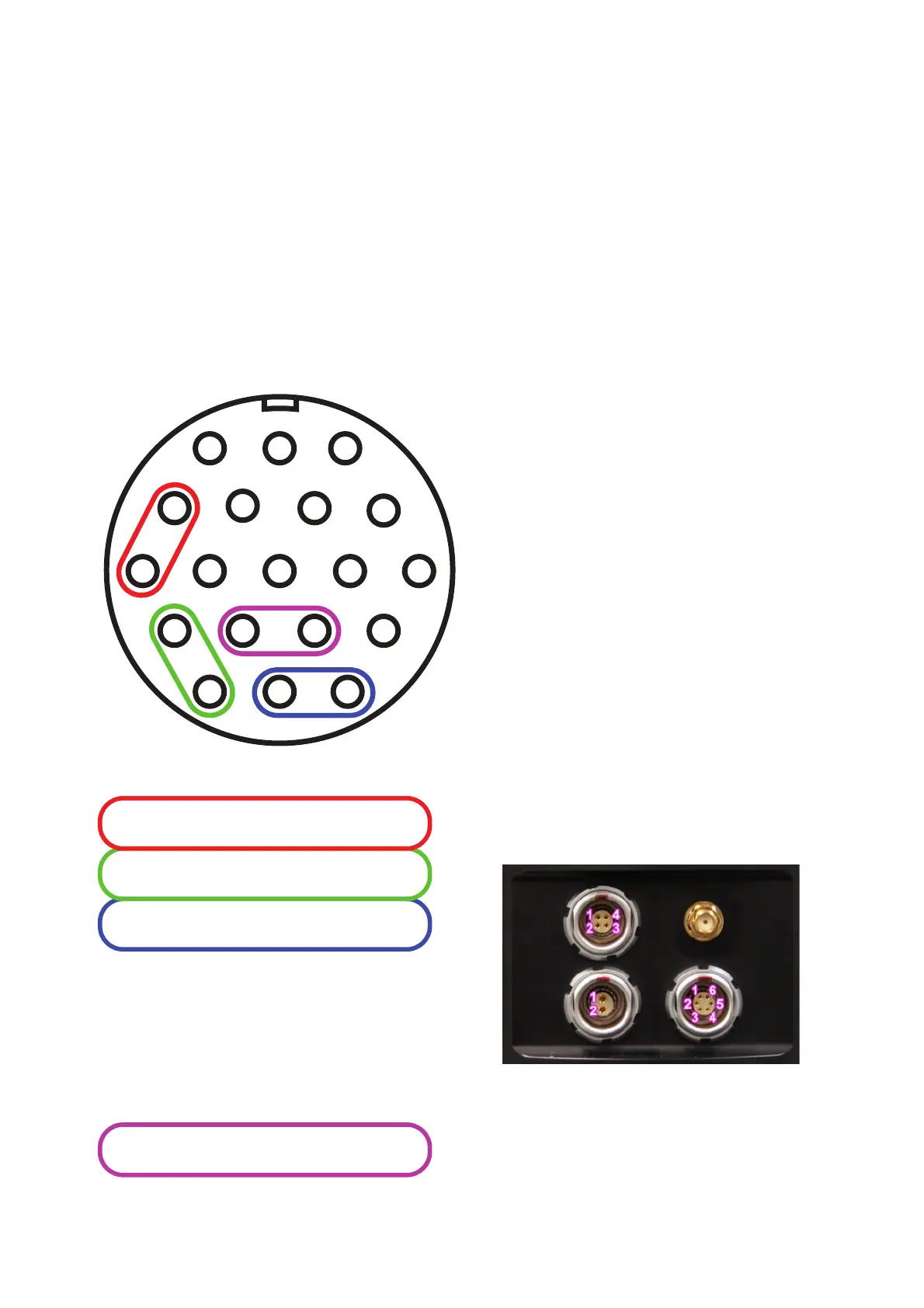
At left is a diagram of the pin connections of
the Gecko sensor port. Looking at the wire-
connection side of the supplied cable plug
shows the same pin configuration. The
function of each pin is listed in the table
below the drawing.
1D Sensor port (mid-
2019 Blast & SMA)
Below is a diagram of the pin connections of
the Gecko Blast and SMA. These models
have a 4-pin socket for an external channel.
Pin 1: O+ signal
Pin 2: O- return
Pin 3: Ground
Pin 4: DC Input Power (+5V optional)
A
D
C
B
HGF
E
M
L
K
JTS
R
P N
UV
A +5V DC
B DC GROUND (power source negative)
C E+ (East-West channel)
D E-
E N+ (North-South channel)
F N-
G Z+ (Vertical channel)
H Z-
J Calibrate Signal
K Calibrate Ground (same as pin B)
L n/c
M DC POWER (power source positive)
N Mass Control – Centre
P Mass Control – Lock
R Mass Control – Unlock
S O+ (Outdoor microphone channel)
T O-
U Calibrate Enable
V Sensor cable overall shield