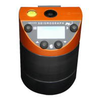
5
Realtime Data Loop – Up Button
Press the Up button from the Home screen to view real time sensor data.
Vector Sum
The first screen shows real time peak sensor output in
sensor units, calculated based on the sensor and gain
settings. Tap the sensor to see the numbers change.
It shows the live peak vector
sum of the 3D sensor, and holds the peak value (max). For
4-channel models, the live data from channel O is shown and
its peak (max) value is also held.
If you have a 3-channel recorder with an accelerometer connected (or have a Gecko SMA
variant) this screen will display an estimate of the Modified Mercalli Intensity (MMI) and
Philippine Earthquake Intensity Scale (PEIS) value based on the maximum displayed
acceleration. Press the Right button twice to clear the retained peak (max) values.
Sensor Signal
Press the Up button again to see the ground motion values
for each sensor axis. Pressing the Right button on this
screen will prompt you to either press the Right button
again to remove any signal offset (it averages the signal for
2 seconds), or press the Down button to clear the any existing offset correction. The Drift
Correction feature (see: 3D Sensor settings) will also correct signal offset over time.
Raw Signal
Pressing Up again will display the raw numbers from the analogue-to-digital converter
(ADC) in real time. The values shown are up to ±8.4 million recorder counts, which
represents a signed 24-bit range number.
The zero level can be controlled in the same way as the
Sensor Signal screen. If you have a 4-channel Gecko, the
date and time line will not be shown, with channel O
appearing at the bottom.
If STA/TA triggering is enabled, the STA/LTA ratio is also displayed in real time at the end of
each line. It is the ratio of the average signal in the short term divided by the average
signal in the long term. When nothing much is happening, this value will sit around 1.0, but
a short burst of anomalous signal will increase the number. This ratio may assist you in
determining at what level to set your STA/LTA trigger threshold.