SCCB TYPE G-202-P00 Service Manual for Producers Page 5
PPUH „GECO” EDITION I PRINTOUT DATE 2014-03-27
III. ORDERING METHOD
The following parameters need to be given in the order, namely:
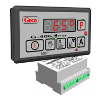
1. Full controller name, e.g. G-202-P00KLB-M1234D
2. The length of tape connecting the executive module and keyboard panel.
3. Temperature sensors lengths.
4. Length of the cable leading to the door opening sensor.
5. Also, door opening sensors can be ordered, operating fully without contact:
magnetic sensor with the range 1-2 cm.
optical sensor with the range 1-2 cm.
IV. DELIVERY, INSTALLATION AND HOOKUP
1. In the appropriate place within the unit cut a hole with dimensions 29x71mm.
2. Executive module should be mounted on the rail and locked by the latch.
For store equipment the SCCB executive module MUST be mounted on the rail set to down towards
the floor!!!
3. Any metal elements, through which the G-202-P00 or its cables are run should be ground or protected
otherwise. Fitting G-202-P00 to enable direct action of water on it (e.g. water condensating on the
bottom cover of the shop window), touching the outlet pipe from the evaporator etc. and changing
considerably its temperature in relation to the ambient temperature (e.g. fitting in the immediate
proximity of the compressor and its accessories, cooled and heated elements) is not allowed.
4. Cut the ribbon connecting the panel with the actuator into the desired length plus 2-3cm. Then, after
running it through all penetrations, cut it once more by cutting its ends at right-angle and clip the plugs
on it so that the end of the ribbon be hidden to approx. 0.5mm. The ribbon must be introduced
perpendicular to the plug and clipped so as to make its twisting or non-parallel layout impossible.
Connecting the ribbon to the connectors (see point XII, drawing 3).
5. After fastening the G-202-P00, connect the power cables according to the description provided on the
actuator wall. Depending on the G-202-P00 version some outputs may be not used - on the label with
the description they will not be described and the type symbol in the corresponding places will contain
zeroes - do not connect any conductors to these outputs!!!
6. The applied connectors are certified for continuous load of 16A!!! They incorporate fine thread and
special lamellae, which prevent the wires from being cut, therefore only light tightening ensures
maximum good contact and the use of greater force may lead to stripping out of the thread. In the
result this may lead to the socket melting and short-circuit !!!
7. Any cable surplus should be cut down or winded up and clamped using special plastic bands. The cables
must be firmly secured on its entire length and must not get in contact with the compressor and its
equipment
8. After connecting the unit to the power source there can be voltage across the lighting cable
regardless of switching on or off the unit with the button therefore the starter or the
fluorescent lamp should be replaced only with the power cord disconnected from the plug!!!
THE SAME APPLIES WHEN CARRYING OUT ANY OTHER REPAIRS !!!

 Loading...