5
1 Link 2
This LED glows bright blue when the Sender Unit and Receiver Unit are
connected using Cat-5 / Cat-6 cable.
2 DVI 2
ThisLEDasheson(brightblue)andoffwhenaDVIvideosourceisconnected
to the Sender Unit. The Sender Unit and Receiver Unit must also be connected
using a Cat-5 / Cat-6 cable.
3 Power Indicator
This LED will turn bright blue once the included 5V DC locking power supply has
been connected and plugged into an available electrical outlet.
4 Link 1
This LED glows bright blue when the Sender Unit and Receiver Unit are
connected using Cat-5 / Cat-6 cable.
5 USB
This LED glows bright blue when a USB source is connected to the Sender Unt.
6 DVI 1
ThisLEDasheson(brightblue)andoffwhenaDVIvideosourceisconnected
to the Sender Unit. The Sender Unit and Receiver Unit must also be connected
using a Cat-5 / Cat-6 cable.
7 Service
Mini-USBserviceportusedforupgradingthermware(primaryboard).
8 Link 1
Connects the Sender Unit to the Receiver Unit using Cat-5 / Cat-6 cable.
9 DVI In 1
Connect a DVI cable from the computer to this DVI-I connector.
10 USB In
Connects a USB cable from this port to the computer.
11 Service
Mini-USBserviceportusedforupgradingthermware(secondaryboard).
12 Link 2
Connects the Sender Unit to the Receiver Unit using Cat-5 / Cat-6 cable.
13 DVI In 2
Connect a DVI cable from the computer to this DVI-I connector.
14 5V DC Locking Power Connector
Connect the included 5V DC locking power supply to this connector.
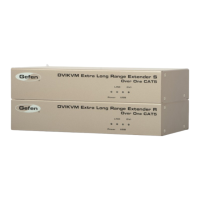
SENDER UNIT DESCRIPTIONS