EasyManua.ls Logo

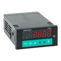
gefran 2400 User Manual

gefran 2400
56 pages
To Next Page IconTo Next Page
Page #1 background imageLoading...
Page #1 background image
1
80290C_MHW_2400_0908_ENG
2400
FAST INDICATOR / INTERCEPTOR
Software version 1.4x
code 80290C / Edition 06 - 09/08 ENG
INSTALLATION AND
OPERATION MANUAL
GENERAL INDEX
Page
Graphic symbols used 2
1 Preliminary instructions 2
General description 2
Basic version
Indicator / Interceptor 2
Options 2
Operator intefrace 3
Electrical interface 3
Preliminary warnings 3
2 Installation and connection 4
Electrical power supply 4
Notes concerning electrical safety and
Electromagnetic compatibility 4
Advice for correct installation
for EMC 5
Instrument power supply 5
Inputs and outputs connection 5
Dimensions and cut-out 6
Installation with panel mounting 6
Warnings and instructions for
mounting to the panel 6
Nominal ambient conditions 6
Electrical connections 7
3 Functions 17
Operator interface 17
General operating notes 18
Navigating through the
Indicator / Interceptor 19
4 Configuration and programming 21
Application notes 39
HOLD function 39
FLASH function 39
Alarms 39
Software ON/OFF switching function 39
String assigned to an alarm 40
5 Technical specifications 41
6 Maintenance 42
Cleaning 42
Repairs 42
Checking the jumpers 42
Troubleshooting Guide 42
7 Technical-Commercial information 43
Order code 43
Accessories
RS232/TTL interface for Gefran
Instrument configuration 43
Appendix 44
Block Diagrams 49
Functional diagram 50
Examples of custom linearization 56
The contents of each section are summarized
immediately following the section heading

Other manuals for gefran 2400

Question and Answer IconNeed help?

Do you have a question about the gefran 2400 and is the answer not in the manual?

gefran 2400 Specifications

General IconGeneral
Display Size5.7 inches
Resolution320 x 240 pixels
Power Supply24 VDC
Input Voltage24 VDC
Display TypeLCD
Input TypeAnalog, Digital
Output TypeAnalog, Digital
Operating Temperature0°C to 50°C
Protection ClassIP65
Protection RatingIP65 (front)
Screen Size5.7 inches

Summary

Preliminary Instructions

Graphic Symbols and General Description

Explains graphic symbols and provides an overview of the instrument's capabilities, inputs, and outputs.

Operator Interface and Electrical Details

Details the front panel interface, electrical terminals, and essential preliminary warnings for safe use.

Installation and Connection

Electrical Power Supply and Safety

Covers power supply requirements, safety requirements, and electromagnetic compatibility guidelines.

Wiring, Mounting, and Environmental Conditions

Guidance on connecting inputs/outputs, panel mounting, warnings, and ambient operating conditions.

Detailed Electrical Connection Diagrams

Comprehensive wiring diagrams for various inputs, outputs, and communication interfaces for different models.

Functions and Operation

Operator Interface Controls

Description of displays, buttons, and LEDs on the instrument's front panel for user interaction.

General Operation and Error Codes

Covers instrument startup, normal operation, self-diagnostics, and interpretation of error codes.

Menu Navigation and Structure

How to navigate through the instrument's configuration menus and understand the parameter structure.

Configuration and Programming

Basic Configuration and Security Settings

Access to menus, password, protection code, and jumper settings for initial configuration.

Input Signal Configuration

Setting up probe types, scale limits, filters, and offsets for all input signals.

Alarm, Output, and Math Function Configuration

Configuration of alarms, outputs, retransmission, and mathematical operations.

Calibration, Linearization, and Hardware Settings

Procedures for user calibration, custom linearization, and hardware parameter settings.

Technical Specifications

Maintenance and Troubleshooting

Troubleshooting Guide and Error Resolution

A guide to identify and resolve common instrument problems and error messages.

Jumper Settings and Instrument Care

Information on checking jumpers, cleaning, and basic maintenance procedures for the instrument.

Technical/Commercial Information

Order Codes and Accessories

Details on instrument order codes, available accessories, and PC configuration software.

Appendix and Diagrams

Parameter Reference

A comprehensive list and description of all instrument parameters, default values, and configuration options.

System Diagrams and Schematics

Block diagrams, functional diagrams, and input/output connection schematics for system understanding.

Related product manuals