Digital input 1 function
Digital input 2 function
SV
F
PV
Digital input 3 function
Digital input 4 function
SV
F
PV
Digital input 5 function
SV
F
PV
Digital input 6 function
SV
F
PV
Digital input 7 function
SV
F
PV
Digital input 8 function
SV
F
PV
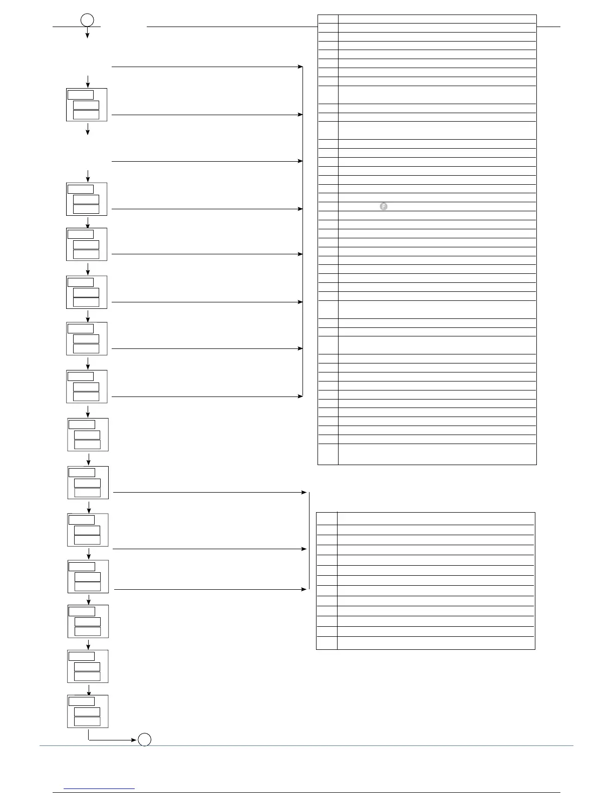
By adding the following numbers to the value shown in the table,
you can enable a series of supplemental functions:
+64: input in denied logic
+128: force logic state 1 (ON)
D
[xrd]
diG.1
diG.2
diG.3
diG.4
diG.5
diG.6
diG.7
diG.8
Function
0 Disabled (no function)
1 Setpoint LOC / REM
2 HOLD IN1
3 Reset alarm latch
4 Selection SP1 / SP2
5 Start / Stop Self Tuning
6 Start / Stop Auto Tuning
7 Set / Reset outputs OUT 1 ... OUT 4
(for diG.1, diG.2 only)
8 Peak ON + (maximum) IN1
9 Peak ON - (minimum) IN1
10 Peak ON - peak
(maximum peak - minimum peak) IN1
11 Reset memory peak IN1
12 Reset memory alarms / peak IN1
13 Selection manual local / automatic
14 Selection manual remote / automatic
15 Check calibration strain-gauge IN1 (6-wire probe)
16 Calibration strain-gauge IN1
17 Software off/on
18 Block key
19 Raise manual local power value
20 Lower manual local power value
21 Raise value of active setpoint
22 Lower value of active setpoint
23 PID group selection - bit0 of (A.Pid-1)
24 PID group selection - bit1 of (A.Pid-1)
25 PID group selection - bit2 of (A.Pid-1)
26 Remoting key F
27 Remoting key INC
28 Remoting key DEC
29 RESET TARE IN1 (only in manual mode and only
from 0 ... 4,2% of input scale)
30 Change color of PV display
31 Power-OFF
33 Reset memory latch + reset disable alarms until first
intercept
34 HOLD IN2
35 Reset memory latch + software on/off
36 Block keyboard
40 Peak ON + (maximum) IN2
41 Peak ON - (minimum) IN2
42 Peak ON - peak (maximum peak - minimum peak) IN2
43 Reset memory peak IN2
44 Reset alarms / peak IN2
47 Check calibration strain-gaugeIN2 (6-wire probe)
48 Calibrate strain-gauge IN2
61 RESET IN2 (only in manual mode and only from
0 ... 4,2% of input scale)
SV
F
PV
PV Digital Filter on PV display
[0.0 ... 9.9] scale points
F1d
Select variable displayed on SV Display in fun-
ction at level 1
Function
0 SSP - active setpoint
1 IN1
2 IN2
3 IN3
4 IN4
5 CO1 - Control output 1
6 CO2 - Control output 2
7 OUTP - Controller output
8 Retransmission output
9 Fin.A
10 Fin.b
11 PV (*)
SV
F
PV
Select variable displayed on F Display in
function at level 1
SV
F
PV
ds.SP
ds.F
E
for ds.SP only, +16 red PV display
Select variable displayed on PV Display in fun-
ction at level 1
Select alarm strings on SV display
[0 ... 1023] bit0 = AL1 ... bit9 = AL10
Select alarm strings on F display
[0 ... 1023] bit0 = AL1 ... bit9 = AL10
Select alarm strings on PV display
[0 ... 1023] bit0 = AL1 ... bit9 = AL10
SV
F
PV
ds.PU
SV
F
PV
Sds.SP
SV
F
PV
Sds.F
SV
F
PV
Sds.PU
(*)The PV visualization never goes over the range limit,
even if +8 in dPS.x is setted.
44 80291G_MHW_2500_08-2010_ENG
44 / 77