dc current
linear input
0 ... 20mA, 4 ... 20mA
• Linear (I)
4
1
2
-
+
• Linear (V)
• PTC / Pt100 2-3 wires
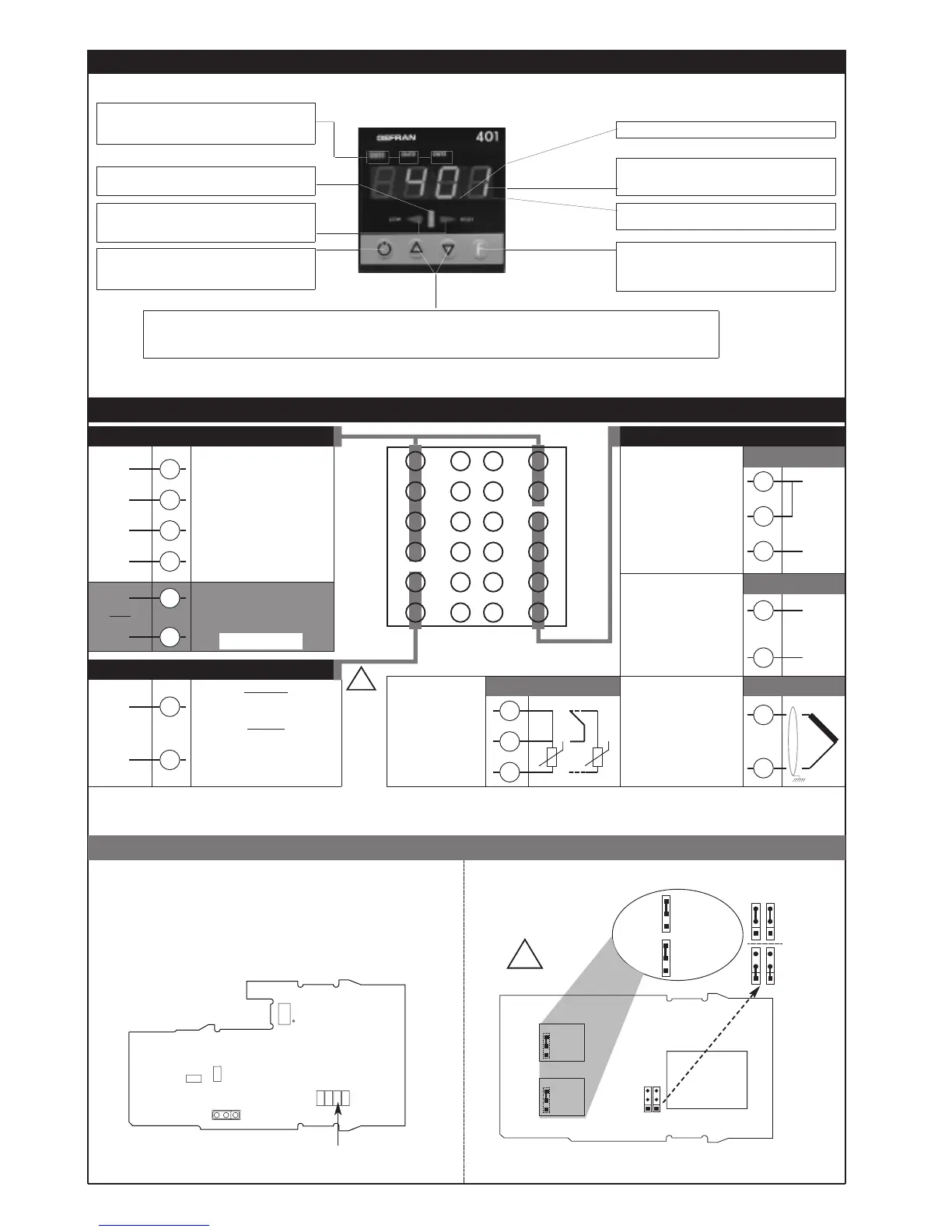
“Raise” and “Lower” keys:
These keys are used for any operation that requires a numerical parameter to be raised or lowered. ••The speed of change is
proportional to the time the key is pressed. •• The operation is not cyclic: once the maximum (minimum) limit is reached, there will be no
further increase (decrease) of the value, even if the key remains pressed.
3 • DESCRIPTION OF FACEPLATE
Automatic/Manual setting selection
In Manual, corresponds to flashing of deviation
indicator
Display
Displays process variable, set point and
configuration parameters
Function key
Gives access to different configuration stages ••
Confirms any parameter changes
Deviation indicator
On if deviation is <0.25% f.s.
Indication of output states
OUT 1 (Main); OUT 2 (AL1); OUT 3 (AL2)
Standard:
100...127Vac (220...240Vac) ±10%
Optional
11...14Vac (22...27Vac) ±10%
11...27Vac/dc (not isolated)
Max. power 5.5VA; 50/60Hz
4 • CONNECTIONS
• Current transformer outputs / inputs
+
-
Generic user-configurable
output
- relay 5A/250Vac
- logic 10V, (20mA/6V)
Rout=100Ω
- relay 5A/250Vac
- logic 5V,Rout=22Ω (4V/20mA)
Current transformer
50mAac, 2Ω 50/60Hz
Available thermocouples:
J, K, R, S, T, B, E, N
- Respect polarities
- For extensions, use
compensated cable
appropriate for
thermocouple.
• Inputs
• TC
Use wires of
adequate thickness
(min. 1mm
2
)
PT100, PTC
6
5
4
3
2
1
7
8
9
10
11
12
18
17
16
15
14
13
19
20
21
22
23
24
2
1
3
1
2
dc voltage
linear input
0...60mV, 0...10V,
12...60mV, 2...10V
2
1
+
-
19
21
20
22
-
+
Out2 (Al1)
-
+
Out1 (Main)
• Power supply
23
24
~
~
TOP
6
5
-
+
Out3 (Al2)
Ing. T.A.
only for mod. 401
!
LED on during Self-tuning or Softstart;
LED flashes during Auto-tuning
LED flashes during software shutdown
PWR
11
Device structure: identification of boards
Pt100 3 wires
PTC / Pt100 2 wires
T
T
Deviation indicator
On if deviation is between 0.25 and 5% f.s.
Flashes if deviation is >5% f.s.
POWER SUPPLY (Components Side)
S3
S2
Jumpers
on Sealing
Side
S2, S3 (LS) = Selection of contacts
NO, NC for Out1/Out2
S1, S4 = Selection of Power Range
220...240Vac
(22...27Vac)
100...127Vac
(11...14Vac)
S4
S1
VH
VL
!
 Loading...


