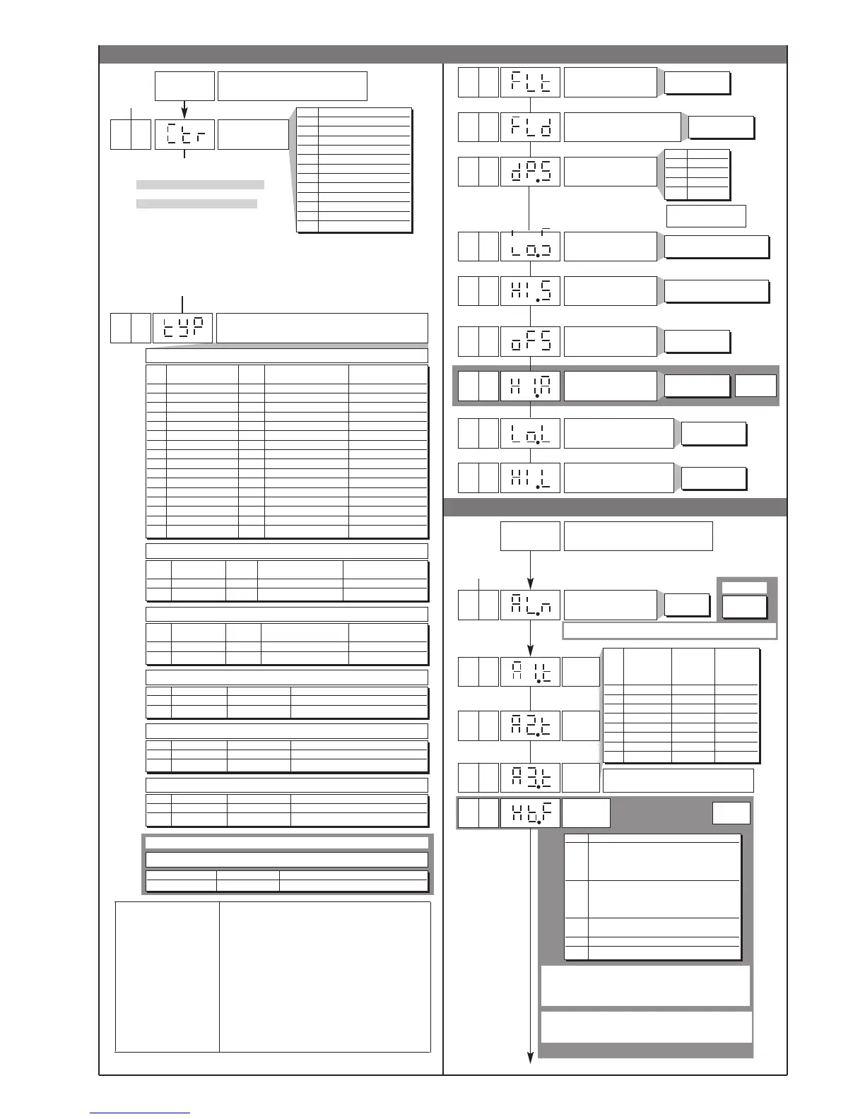
• Out
• InP
Lo.S ... Hi.S
Type of probe, signal and scale of main input
tYP Type of probe Scale Max. scale range Max. scale range
(C/F) without decimal point with decimal point
0 J (Fe-CuNi) C 0 / 1000 0,0 / 999,9
1 J (Fe-CuNi) F 32 / 1832 32,0 / 999,9
2 K (NiCr-Ni) C 0 / 1300 0,0 / 999,9
3 K (NiCr-Ni) F 32 / 2372 32,0 / 999,9
4 R (Pt13Rh - Pt) C 0 / 1750 0,0 / 999,9
5 R (Pt13Rh - Pt) F 32 / 3182 32,0 / 999,9
6 S (Pt10Rh - Pt) C 0 / 1750 0,0 / 999,9
7 S (Pt10Rh - Pt) F 32 / 3182 32,0 / 999,9
8 T (Cu-CuNi) C -200 / 400 -199,9 / 400,0
9 T (Cu-CuNi) F -328 / 752 -199,9 / 752,0
10 B (Pt30Rh - Pt6Rh) C 44 / 1800 44,0 / 999,9
11 B (Pt30Rh - Pt6Rh) F 111 / 3272 111,0 / 999,9
12 E (NiCr-CuNi) C -100 / 750 -100,0 / 750,0
13 E (NiCr-CuNi) F -148 / 1382 -148,0 / 999,9
14 N (NiCrSi-NiSi) C 0 / 1300 0,0 / 999,9
15 N (NiCrSi-NiSi) F 32 / 2372 32,0 / 999,9
tYP Type of probe Scale Max. scale range Max. scale range
(C/F) without decimal point with decimal point
16 PT100 C -200 / 850 -199,9 / 850,0
17 PT100 F -328 / 1562 -199,9 / 999,9
SENSOR: RTD 3 wires (CAL = 2)
tYP Type of probe Scale Max. scale range Max. scale range
(C/F) without decimal point with decimal point
18 PTC C -55 / 120 -55.0 / 120.0
19 PTC F -67 / 248 -67.0 / 248.0
SENSOR PTC (CAL = 3)
tYP Signal type Scale Max. scale range
20 0...60mV linear -1999 / 9999
21 12...60mV linear -1999 / 9999
SENSOR: VOLTAGE 60Mv (CAL = 4)
tYP Signal type Scale Max. scale range
22 0...20mA linear -1999 / 9999
23 4...20mA linear -1999 / 9999
SENSOR: CURRENT 20mA or TRANSMITTER (CAL = 5)
tYP Signal type Scale Max. range scala
24 0...10V linear -1999 / 9999
25 2...10V linear -1999 / 9999
SENSOR: VOLTAGE 10V or TRANSMITTER (CAL = 6)
InP
Input settings
Minimum limit of main
input scale
Maximum limit of main
input scale
Main input offset
correction
Lower limit for local setpoint
and absolute alarms
SENSOR: TC (CAL = 1)
min…max scale of input
selected in tyP
min…max scale of input
selected in tyP
-999 ... 999
scale points
Lo.S ... Hi.S
Upper limit for local setpoint
and absolute alarms
Type of control
[0...91]
CtrL Type of control
0 P hot
1 P cold
2 P hot / cold
3 PI hot
4 PI cold
5 PI hot / cold
6 PID hot
7 PID cold
8 PID hot / cold
9 ON-OFF hot
10 ON-OFF cold
11 ON-OFF hot / cold
0
0
1000
22
Default Custom
Configurat.
0,0...99,9
Max. current transformer
input scale
Out
Output settings
+ 8 to disable on power-up until first alarm
AL.x Direct Absolute Normal
(maximum) Relative Symmetrical
Inverse to active (window)
(minimum) setpoint
0 direct absolute normal
1 inverse absolute normal
2 direct relativo normal
3 inverse relativo normal
4 direct absolute symmetrical
5 inverse absolute symmetrical
6 direct relativo symmetrical
7 inverse relativo symmetrical
0 ... 3
Number of alarms
Alarm
type 1
Alarm
type 2
Alarm
type 3
Default Custom
Configurat.
0
4, 5, 6 to select HB alarm as alternative to alarm 3
Function of
HB alarm
+0 assigned to OUT1 (only for Hb_F = 0, 1, 2)
+4 assigned to OUT2 (only for Hb_F = 0, 1, 2)
+16 alarm HB reverse
Hb_F Description
0 Relay, logic output: alarm active
with load current value below
limit set in ON time
of control output
1 Relay, logic output: alarm active
with load current value above
limit set in OFF time
of control output
2 Alarm active if one of functions 0 and 1
is active (OR logic for functions 0 and 1) (*)
3 Alarm HB continuous heating (**)
7 Alarm HB continuous cooling (**)
mod. 401
mod. 401
With mod. 401, set CAL=7 to calibrate the current transformer input
SENSORE TA: CORRENTE 50mAac (CAL = 7)
Signal type Scale Max. range scala
0 ... 50mAac linear 0 ... 99,9
0 ... 6
mod. 400
mod. 401
+16 disable parameters
CFG: rst, PrE, SoF, Lbt, Lbp, FAP,
HY.2, HY.3 (only for model 400)
InP: FLt, FLd, oFS, LoL, HIL
Out: ALn, A2t, A3t (only for model 400), rEL
FLt, FLd, oFS stay at set value.
ALn is forced to 1 (only for mod. 400)
All other parameters are considered 0.
14
Default: derived action sample time = 1 sec
+32: derived action sample time = 8sec
+64: derived action sample time = 240msec with derived action filter assigned
to Flt parameter (time filter)
(*) minimum limit is set = 12.5% of current transformer f.s.
(**) As type 0 without reference to cycle time .
Digital filter
on main input
Digital filter on display of
process variable; acts as
hysteresis
Decimal point position for
main input scale
(*) not available for
TC, RTD, PTC scales
0,0 ... 20,0 sec
0 ... 9,9
scale points
dP.S Format
0 xxxx
1 xxx.x
2xx.xx (*)
3x.xxx (*)
0
Max. non-linearity error
for thermocouples (TC),
resistors (PT100) and
thermistors (PTC).
The error is calculated
as deviation from
theoretical value and is
expressed as
percentage of full scale
(in °C
S, R range 0...1750°C; error < 0.2% f.s. (t > 300°C) /
for other range; error < 0.5% f.s.
T error < 0.2% f.s. (t > -150°C)
B range 44...1800°C; error < 0.5% f.s. (t > 300°C) /
range 44,0...999,9; error < 1% f.s. (t > 300°C)
Tc:
J, K, E, N, error < 0,2% f.s.
PTC error < 0,2% f.s.
PT100 scale -200...850°C
Precision better than 0,2% f.s. at 25°C
 Loading...


