This type of alarm is conditioned by use of the current transformer input. (T.A.)
It signals variations of load absorption by discriminating the level of current at the transformer input in the range (0...HI.A). It is
enabled with configuration code (AL.n); in this case the alarm trip value is expressed in HB scale points.
Select the type of functioning and the assigned control output by means of code Hb.F (“Out” phase).
The alarm limit setting is A.Hb.
The direct HB alarm trips if the value of the current transformer input is below the set limit for Hb.t seconds inclusive of “ON”
time of the selected output.
The HB alarm can be activated only with ON times longer than 0.4 seconds.
HB alarm function also includes control of load current in the OFF interval of the cycle time for the selected output: the HB
alarm will trip if the measured current exceeds approximately 12.5% of the full scale set (parameter HI.A in InP) for Hb.t
seconds inclusive of the OFF state of the output.
The alarm is reset automatically if the cause of the alarm is eliminated.
Setting a limit of A.Hb = 0 disables both types of HB alarms, with de-energizing of the assigned relay.
Indication of load current is displayed by selecting term C.T. (level 1).
NOTE: ON/OFF times refer to the cycle time set for the selected output.
Alarm Hb_F = 3 (7) continuous is active for a load current value below the set limit; it is disabled if the value of the
heating(cooling) output is less than 2%.
FUNCTION OF HB ALARM (only for mod. 401)
Fault action
(definition of state
in case of broken
sensor) alarms
AL1, AL2, AL3.
Select intrinsic
safety.
1) In case of broken sensor, the logic state of the alarm assumes the logic value selected without consideration of
alarm type (direct or reverse): ON = alarm active, OFF = alarm inactive.
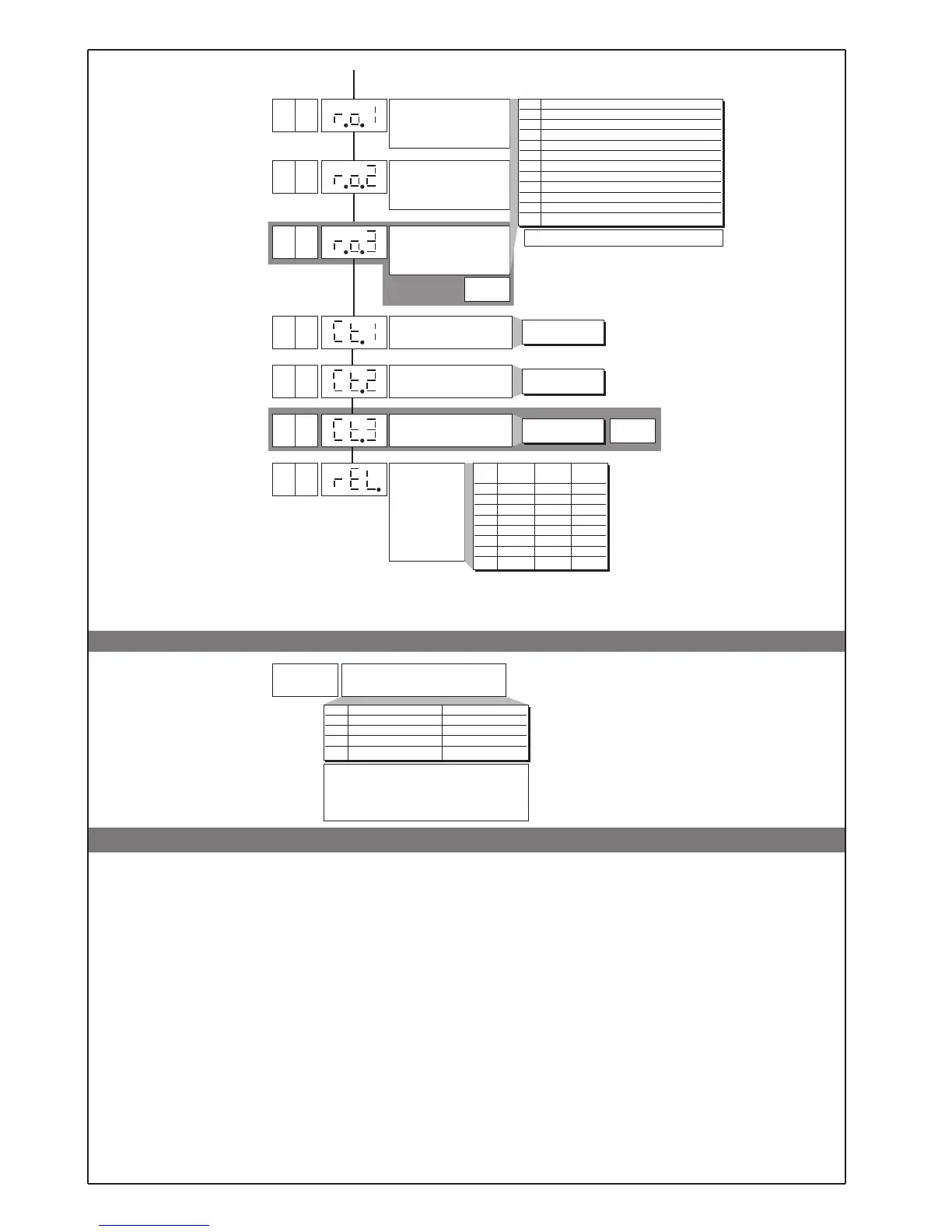
2) Alarms are assigned to available outputs by setting codes r.o.1, r.o.2, r.o.3.
rEL Alarm Alarm Alarm
123
0 OFF OFF OFF
1 ON OFF OFF
2 OFF ON OFF
3 ON ON OFF
4 OFF OFF ON
5 ON OFF ON
6 OFF ON ON
7ONONON
Cycle time OUT1 relay or
logic = HEAT or COOL
Cycle time OUT2 relay or
logic = HEAT or COOL
1. ... 200 sec
1. ... 200 sec
10
Cycle time OUT3 relay or
logic = HEAT or COOL
1. ... 200 sec
• Prot
Pro
Protection code
Pro Display Change
0 SP, alarms, OutP SP, alarms
1 SP, alarms, OutP SP
2SP SP
3SP
+4 disables InP, Out
+8 disables CFG
+16 disables “SW turn on - turn off”
+32 disables MAN/AUTO key
+ 64 to disable manual power modification
mod. 401
To activate the turn off SW function, press keys F
F +
∆ for 5 secs. in P.V.
To return to normal functioning, press key F for 5
secs.
15
OUT 1
Attribution of reference
signal: HEAT, COOL, AL1,
AL2, AL3
+ 16 for logic level denied at output
OUT 2
Attribution of reference
signal: HEAT, COOL, AL1,
AL2, AL3
r.o.x MAIN logic output function, relay (OUT1)
0 HEAT (heating control output)
1 COOL (cooling control output)
2 AL1 - alarm 1
3 AL2 - alarm 2
4 AL3 - alarm 3 [A.Hb mod. 401])
5-
6 LBA - alarm LBA
7 (AL1) OR (AL2)
8 (AL1) OR (AL2) OR (AL3 [A.Hb mod. 401])
9 (AL1) AND (AL2)
10 (AL1) AND (AL2) AND (AL3 [A.Hb mod. 401])
2
0
OUT 3
Attribution of reference
signal: HEAT, COOL, AL1,
AL2, AL3
mod. 401
N.B. When T.A. input is present, Out3
(if configured) is limited to indication of
corresponding LED.
 Loading...


