3 • FUNCTIONS
his section describes the use and functions of the displays, lighted indicators and buttons making up the
controller operator interface.
It therefore contains essential information for correct programming and configuration of the controllers.
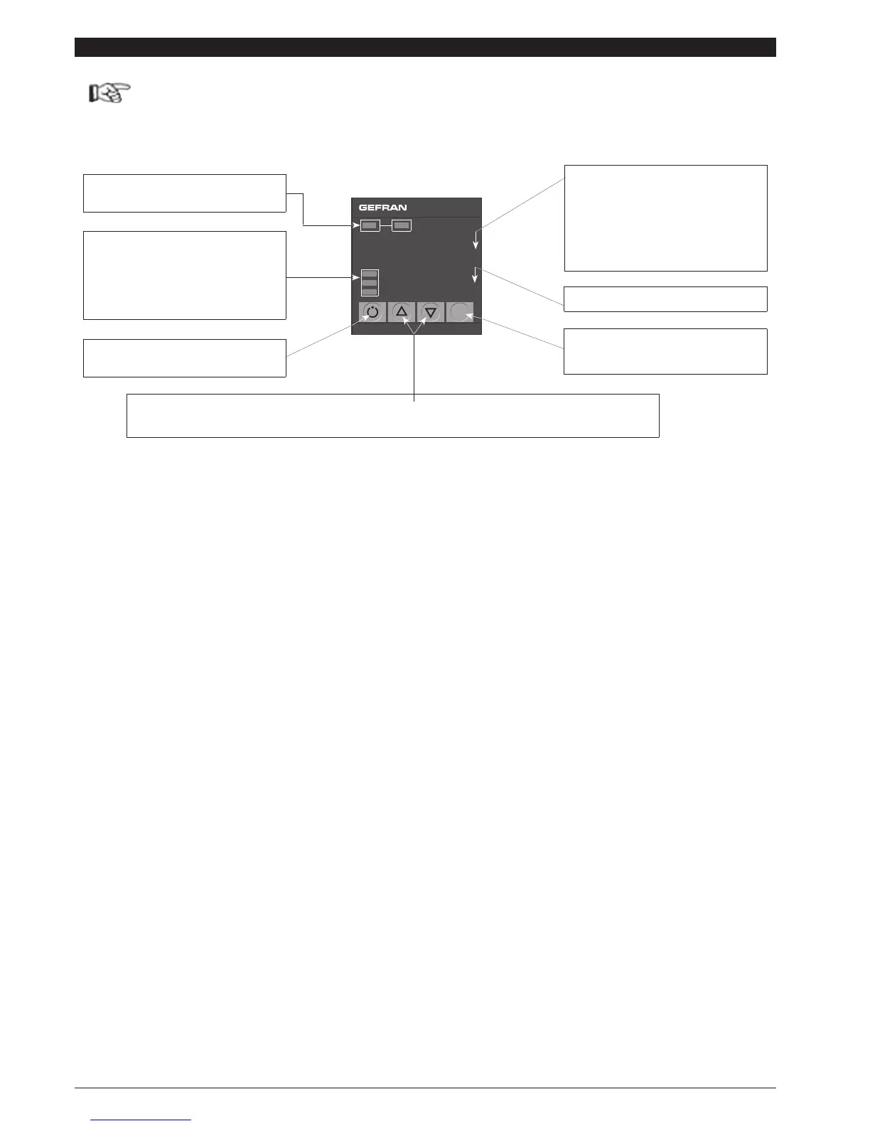
Operator interface
“Raise” and “Lower” keys”
These keys are used for any operation that requires a numerical parameter to be raised or lowered. ••The speed of change is
proportional to the time the key is pressed. •• The operation is not cyclic: once the maximum (minimum) limit is reached, there will be no
further increase (decrease) of the value, even if the key remains pressed.
Automatic/Manual setting selection
On only when PV display shows process variable
PV Display: Indication of process variable
Error Indication: LO, HI, Sbr, Err
LO= the value of process variable is < di LO_S
HI= the value of process variable is > di HI_S
Sbr= faulty sensor or input values higher than max.
limits
Err= PT100 third wire opened for PT100, PTC or
input values lower than min. limits (i.e.: TC wrong
connection)
Funktion key
Gives access to different configuration stages ••
Confirms any parameter changes
Indication of output states
OUT 1 (Main); OUT 2 (AL)
SV Display: displays control Setpoint
Function displays
Display instrument function mode
L1 MAN/AUTO = OFF (automatic control)
ON (manual control)
L2 AUTO-TUNING = ON (auto-tuning ON)
L3 SELF-TUNING/
SOFT-START= ON (during self-tuning or
soft-start).
450
OUT1
OUT2
SV
L1
L2
L3
 Loading...