1S9STOEN_26-5-17_ADL300_STO_STO Pag. 17/30
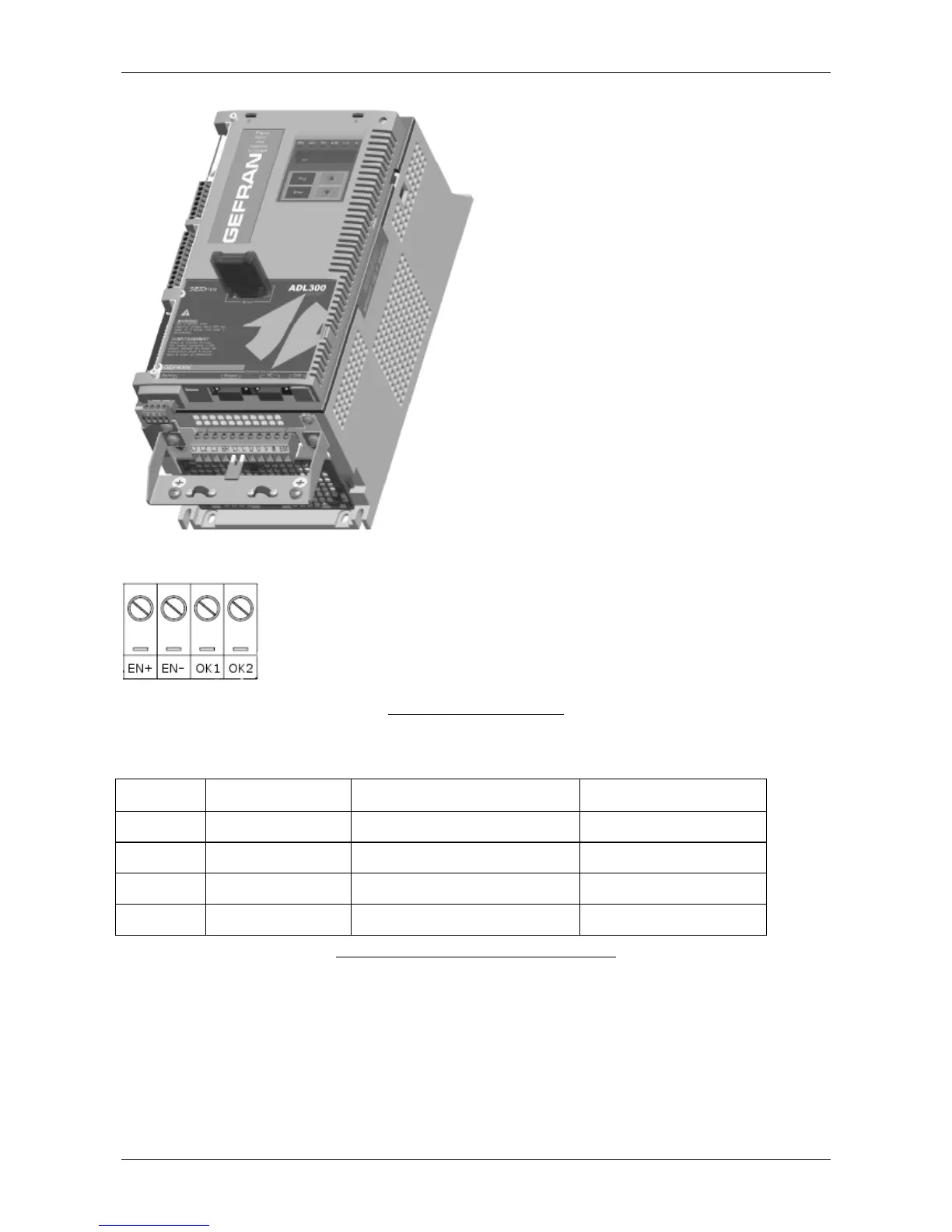
Safety connector layout is shown in Figure 6
Figure 6 Safety Connector Layout
Table 3 is a description of signals onto Safety Connector.
Signal name Function Description Electrical limits and range
EN+ +SAFETY ENABLE
+24v for disabling the safety
function
(IN) +12…+35v with respect
to EN-
0v COM for disabling the safety
function
Normally closed contact for Safety
feedback (contact 1)
250mA maximum DC current
OK2 SAFETY OK2
Normally closed contact for Safety
feedback (contact 2)
250mA maximum DC current
Table 5 Description of Signals onto Safety Connector.
Concerning the Regulation signals, the interface is more complex given the number of available
conFiguretions for ADL300:
- ADL300 Basic the ENABLE signal is fixed onto the regulation board interface is shown in
Figure 8 and Table 6.
- ADL300 Advanced, ENABLE and feedback signals are placed onto the ADL-IO expansion
card. ADL-I/O optional cards are listed in Appendix A.2 of Specification and Installation
User manual. Figure 10 and Table 7 show a sample example of ADL300 conFiguretion and
safety related pin description.
 Loading...


