1S9STOEN_26-5-17_ADL300_STO_STO Pag. 8/30
4 Safety system description
Safe Torque Off safety function is integrated into the drive family ADL300, and is managed by
means of two enable signals “ENABLE” and “SAFETY ENABLE”.
4.1 Device functionality and architecture
The system herein examined are Power Drive Systems (PDs) also called Inverter. A PDS is power
device connected one side to the mains (three-phase system) and on other side to the motor
power lines. Motor and other devices which are related to the system functionalities (relays, cables
The PDS makes the motor move according to the settings operator has defined.
From the electrical point of view PDS takes power from mains to the motor lines.
Inverter device family called ADL300 is subject of this document. From the safety and main
functionality points of view all devices of the family can be modeled as the same thing, herein
represented in Figure 1.
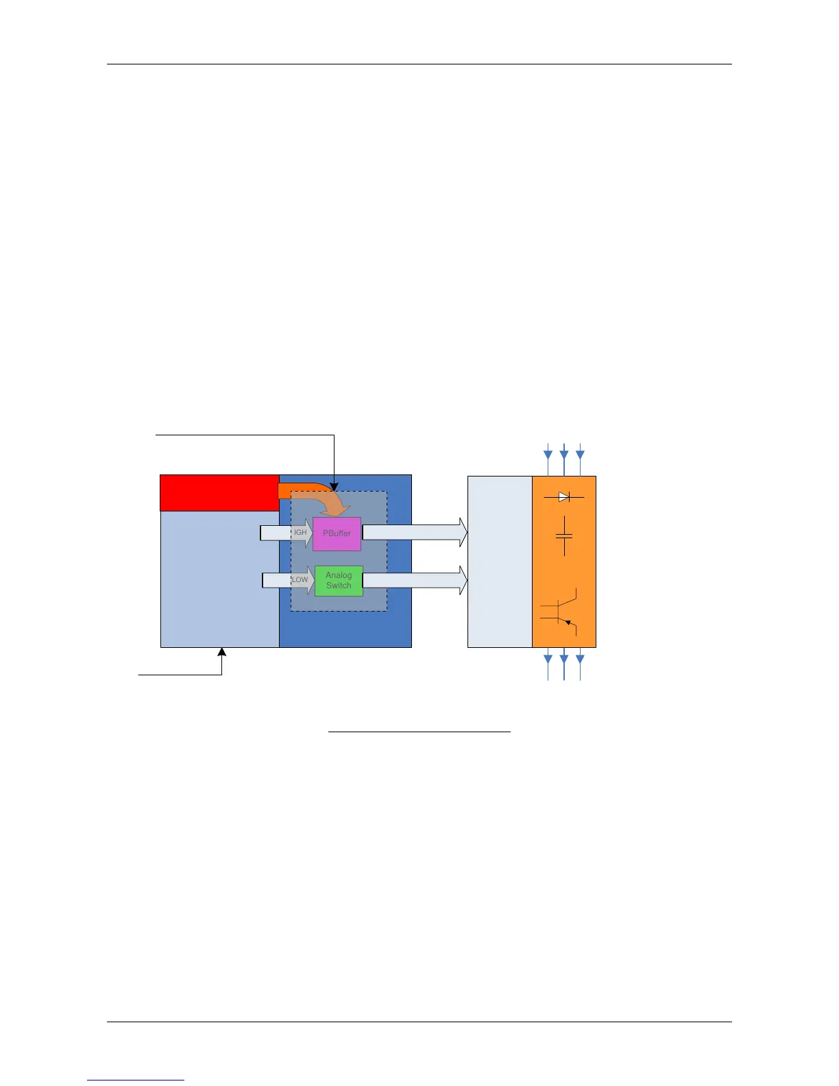
Figure 1 block diagram of PDs ADL300.
All ADL300 PDs are integrated PD devices featuring different power ratings, dimensions as well as
enclosures. Though from the functional and electrical points of view all devices are made up of the
same fundamental four parts:
1. Regulation board
2. Driver board
3. IGBT power module
4. Safety part
Follows a brief description of four parts:
Regulation board: exists as separate PCB, main purpose of this board is to generate
coordinated PWM pulses going to the IGBT gates. PWM pulses are controlled and
generated by the software according to the settings to provide given voltage, current,
motor speed, motor acceleration, etc options. PWM pulses can be cancelled out
directly onto the regulation board by means of a PWM inhibit signal which acts directly