93-E
—————— MANUAL DE INSTRUCCIONES ——————
2.3. DESCRIPCIÓN DE LOS BORNES DE POTENCIA
2.4. DESCRIPCIÓN DE LOS BORNES DE CONTROL
Terminals
U, V, W
C
D
U3, V3
Function
Power supply via AC mains, 3Ph (400V –15% up to 480V +10%)
Positive terminal to be connected to the inverter DC-LINK
Negative terminal to be connected to the inverter DC-LINK
Supply for internal fan (only for 1050A size and higher) (1Ph, 230V ± 15%)
Terminals
23
32
33
34
35
36
37
52
70, 72
81, 82
Function
Input of the precharge enable control
Output of the MLP static signal (low - active signal)
(Common) Ground of the MLP and ML static signals
Reference point for Power supply +24V
Power supply output +24V
Output of the ML signal (low - active signal)
Power supply of the ML and MLP signals
(Common) Ground of the precharge enable control
OK Relay
Blown fuse.
On SM32-480-1050, 1500 and 2000A sizes only.
Voltage, Current
(15 - 35V, 5 - 11mA)
(5 … 35V, 20mA source)
-
-
(32V / 300mA max)
(5 … 35V, 20mA max sink)
(35V max)
-
(max 250VAC, 1A – AC11)
(max 250VAC, 1A – AC11)
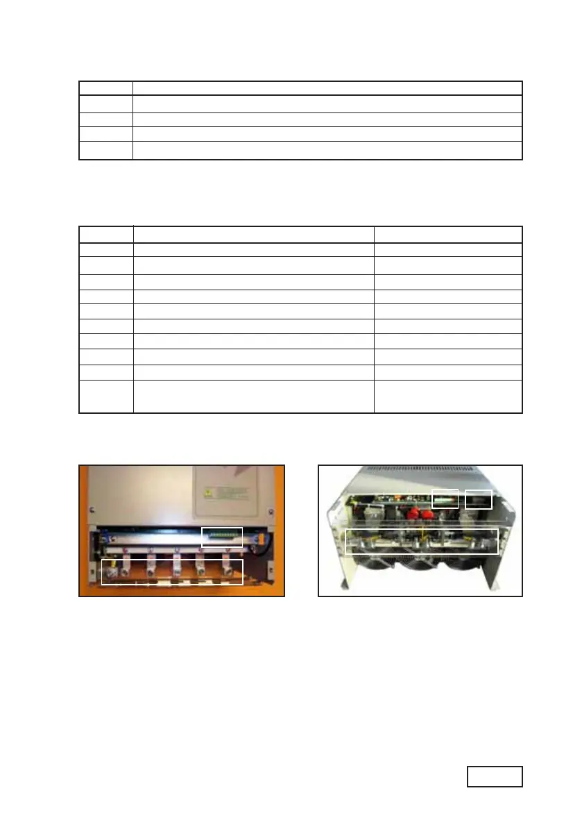
Figura 2.4.1: Localización de los bornes
a) = bornes de control
b) = bornes de potencia
c) = bornes de potencia (U3, V3) y bornes de control (81, 82)
Taglie 185 ... 650 A
a)
b)
Taglie 1050 ... 1500 A
a)
b)
c)