www.gemu-group.com38 / 46GEMÜ 550
11 Pneumatic connections
11 Pneumatic connections
The product has 2 control medium connectors.
Control function Control medium
connector 2 (open)
Control medium
connector 4 (close)
1 (NC) + -
2 (NO) – +
3 (DA) + +
+ = available
– = not available
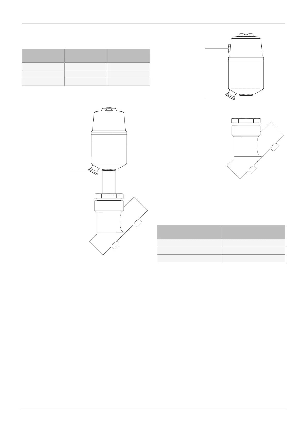
Control medium connector 2
Fig.9: GEMÜ 550, control function 1
Control medium connector 4
Control medium connector 2
Fig.10: GEMÜ 550, control function 2 and 3
1. Use suitable connectors.
2. Connect the control medium lines tension-free and
without any bends or knots.
3. The actuator can be rotated 360°. The control medium
connectors can be in any position.
Actuator size Thread size of the control
medium connectors
0 M5
1, 2 G 1/8
3, 4, 5 G 1/4
11.1 Use of pilot valves in gas applications
When using the valve in gas applications (order code Special
function G), the closing time must be less than 1 s.
GEMÜ recommends the GEMÜ 8500 pilot valve.