www.gemu-group.com42 / 46GEMÜ 550
15 Inspection and maintenance
15.3 Removing the actuator
1. Move the actuator A to the open position.
2. Undo union nut a.
3. Remove actuator A from valve body 1.
4. Disconnect actuator A from the control medium lines.
5. Clean all parts of contamination (do not damage parts dur-
ing cleaning).
6. Check parts for potential damage, replace if necessary
(only use genuine parts from GEMÜ).
15.4 Replacing the seals
NOTICE
Gasket!
● Replace gasket 4 each time the actuator is disas-
sembled/assembled.
1. Remove actuator A (see chapter "Removing the actuator").
2. Remove sealing washer 4 from the valve body.
3. Loosen nut e on spindle b (hold spindle b with appropriate
tool that will not damage the spindle surfaces).
4. Remove retaining washer d.
5. Remove seat seal 14.
6. Clean all parts of contamination (do not damage parts dur-
ing cleaning).
7. Insert new seat seal 14.
8. Insert retaining washer d.
9. Apply appropriate thread locking compound on the thread
of spindle b.
10. Fix spindle b in place with nut e (hold spindle b in place
with appropriate tools which do not damage the spindle
surfaces).
11. Insert new sealing washer 4 in valve body 1.
12. Mount actuator A (see chapter "Mounting the actuator").
15.5 Mounting the actuator
CAUTION
Incorrect combination of actuator and
valve body!
▶ Risk of damage to the actuator and
valve body.
● For control valves with a reduced valve
seat, make sure that the combination
of actuator and valve body is correct.
● Compare the product label of the actu-
ator with the valve body marking.
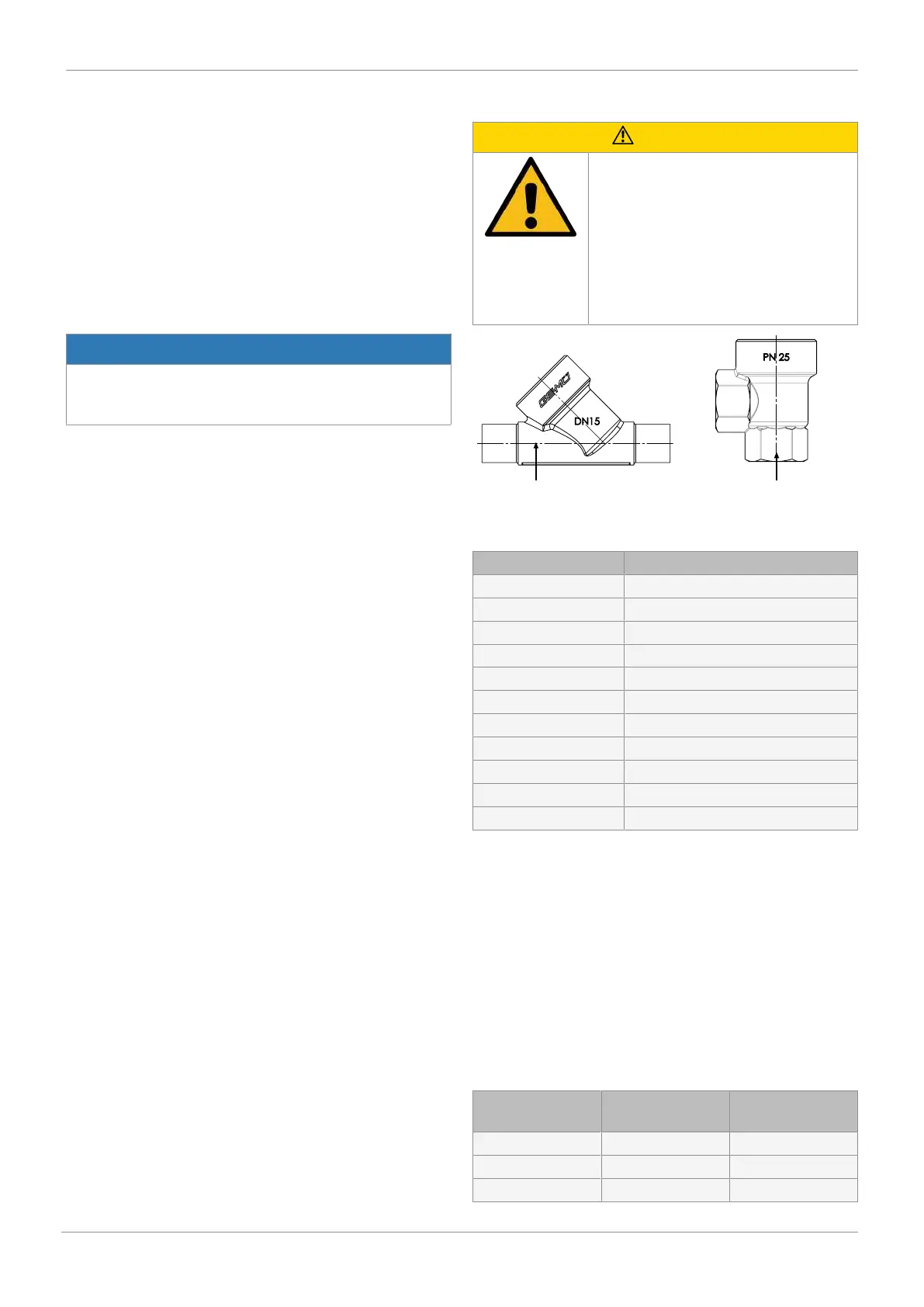
Valve body marking 2/2-way
body
Valve body marking: Angle
valve body
Fig.12: Valve body marking
Actuator product label Valve body marking
RAxxx R002
RBxxx R004
RCxxx R006
RDxxx R008
RExxx R010
RFxxx R012
RGxxx R015
RHxxx R020
RJxxx R025
RKxxx R032
RMxxx R040
1. Move the actuator A to the open position.
2. Lubricate the thread of union nut a using a suitable lubric-
ant.
3. Place actuator A on valve body 1 approx. 90° anticlock-
wise to the end position of the control medium connectors
and screw it in hand tight using union nut a.
4. Tighten union nut a with an open-end wrench (for torques,
see table). This rotates actuator A clockwise approx. 90°
to the desired position.
5. Move the actuator A to the closed position.
6. With the valve fully assembled, check the function and
tightness.
Nominal size
[DN]
Actuator size Torque
[Nm]
DN 6 0G / 0M 35
DN 8 0G / 0M 35
DN 10 0G / 0M 35