Do you have a question about the Gemini DS-2024 and is the answer not in the manual?
Lists microphone, phono, line inputs, output, impedance, sampler system, dimensions, and weight.
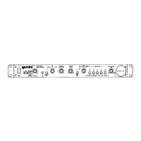
Identifies and labels the controls on the front panel of the DS-2024 sampler.
Step-by-step guide for connecting microphones, line inputs, outputs, and headphones to the sampler and mixer.
Instructions for powering on the unit and selecting input sources using the SOURCE SELECTION switch.
Details on how to record samples, including selecting memory banks and using the START/STOP button.
Explains how to play back samples in single or repeat modes using the START/STOP button.
Guide for sampling audio directly from a microphone, including indicator lights.
Describes the Robo Play feature, how it interacts with selected sources and mutes them.
Explains how to adjust sampler level, pan, cue mode, and pitch controls for optimal sound.
Provides helpful hints for using the pitch control during recording and playback for desired effects.
Details the battery backup feature for sample retention and the low battery indicator function.
Steps to remove the top case and front panel, including specific screws and knobs.
Instructions for removing the sampler PCB, bottom cover, and various supporting components.
Guides on removing main PCB, effect PCB, LED PCB, start/stop PCB, mic PCB, and transformer.
Steps for detaching the battery holder from the unit.
Internal diagram and pinout for the NJM4558 integrated circuit.
Logic symbol and diagram for the SN4/74LS74A integrated circuit.
Pinout and diagrams for commonly used transistors.
Pinout and diagram for the 2SA1317 transistor.
Diagrams and pinouts for NJM78M00 and NJM79M00 voltage regulator ICs.
Internal circuit diagram for the NJM4558DX operational amplifier.
Pinout for the SN4/74LS00 integrated circuit.
Internal circuit diagram for the NJM7805FA voltage regulator.
Block diagram and pinout for the MSM6388GS-VIK integrated circuit.
Block diagram and pinout for the MSM6389RS integrated circuit.
Illustrates wiring for AC input, fuse, power switch, transformer, and battery holder.
Shows connections to the main PCB, power LED, and sampler mic.
Details wiring between the sample PCB, sampler select PCB, and other boards.
Illustrates wiring for Robo Play, Bank LED, and Start/Stop PCBs.
Schematic details for input selection and audio signal flow through the unit.
Schematic details of control logic, power supply, and operational circuits.
Detailed schematic for the Sampler PCB, including component values.
Schematic of pitch control, mode selection, battery, and power LED circuits.
Explains component notations like F, pF, K, M, and voltage ratings.
Visual layout diagrams for the Main PCB and Sample PCB.
Visual layout diagrams for the Power LED PCB and Sampler Select PCB.
Visual layout diagrams for Bank LED, Start/Stop, Sampler Mic, and Robo Play PCBs.
Lists part numbers and descriptions for various diodes and zener diodes used in the unit.
Lists part numbers and descriptions for all integrated circuits used in the unit.
Lists part numbers and descriptions for all transistors used in the unit.
Lists part numbers and descriptions for resistors and capacitors.
Lists remaining capacitors, connectors, and packing materials with their part numbers.
| Brand | Gemini |
|---|---|
| Model | DS-2024 |
| Category | Recording Equipment |
| Language | English |