L
NAPCO Security Systems
X
GEM-P9600 Installation Instructions
WI742E 2/04
!
Page 45
for each telephone number used, but a different format may be assigned to each.
Refer to Backup Report on Telco 2 and Report Telco 3 to determine whether or not Telephones 2 and/or 3 will be programmed.
Call the central station for each telephone number used to confirm the type of receiver in use. Select the receiver format entry for
each telephone number from the following table.
*These formats do not use programmable codes, but Event ID Codes to identify the type of zone as follows:
1 – Fire
2 – Panic
3 – Burglary
4 – Holdup
7 – Gas Alarm
8 – Heat Alarm
A – Auxiliary Alarm (keypad displays “0”)
B – 24-Hour Auxiliary Alarm
Relay Control
(External Relays)
In addition to the three relays provided on the motherboard, up to 24 external relays (8 per RB3008 Relay Module) or X-10 de-
vices (24 per GEM-X10 module) may be controlled from the keypad, by event or by schedule through the use of PCD-Windows
downloading software. Program these outputs to activate by event on PCD-Windows External Relay Control screen, or by schedule
on the Event Scheduler screen.
Relay Follows Zone
External Relays can be programmed to follow an open or shorted zone. On the PCD-Windows External Relay Control screen,
program the External Relay to “follow “ an open zone, or to “follow” a shorted zone.
Relay Outputs See Alarm Outputs
Relay / X-10 Mapping
It is possible to have a relay or X-10 device activate for multiple events, with a maximum of 24 events. This allows the relay or X-
10 device to be activated by multiple events or conditions. This is programmed by assigning or mapping events to relay numbers.
PCD Windows must be used to program Relay/X-10 mapping. Referring to the PCD-Windows External Relay Control screen, the
“Relay / Entry#” column typically indicates the number of the relay which will accept the commands on that line. However, the “Map”
column, which is used to transfer the function defined on that line to a device on another line.
Remote Panic See Panic Zone
Report Digital Dialer Exit Error/Recent Closing
(SIA CP-01 Requirement: 4.2.2.6)
A Recent Closing transmission is sent if an alarm occurs within two (2) minutes after the expiration of the Exit Time. If the user num-
ber is available, it is included in the Recent Closing transmission. Note: Recent Closing transmissions are not sent for fire alarms.
Report Telco 1
Report Telco 3 (Double or Split Reporting)
Alarms, alarm restores, troubles and trouble restores may be selected individually for each zone. Violation of a zone selected to
report will communicate the code(s) selected for that zone to the central station.
Normally, Report Telco 1 is used to report to the central station. Report Telco 3 is used when certain zones will report to a differ-
ent receiver (split reporting); Report Telco 1 and Report Telco 3 are both used on the same zone to report to two receivers succes-
sively (Double Reporting). (Double Reporting requires a successful report to Telco 1 before reporting to Telco 3). Also see Backup
Report on Telco 2.
Reset Day Zone with Arm/Disarm Only See Day Zone
Reset Relay See Alarm Outputs
GLOSSARY
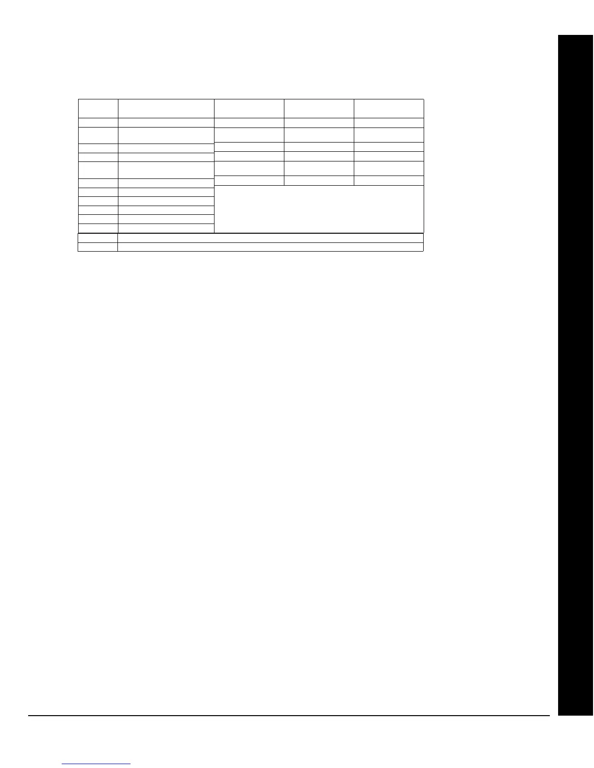
ENTRY RECEIVER FORMAT
(blank) Ademco, Silent Knight Slow
1 Sescoa, Vertex, DCI, Franklin
Fast
2 Radionics Fast
3 Silent Knight Fast
4 Radionics, DCI, Franklin
Slow
5 Universal Hi-Speed
8 Radionics BFSK
9 FBI 4/3/1*
A Radionics Modem 2*
B SIA*
C Ademco Point ID*
DATA FREQ. (Hz) DUTY CYCLE
(ON/OFF)
INTERDIGIT TIME
1900 60/40mS 600mS
1800 30/20 800
1850 13/12 400
1900 40/30 560
1800 60/40 600
1850 30/20 350
Modem Formats
D Ademco Express (Touch-tone 4/2 Format)
0 Radionics Modem IIe
 Loading...