EasyManua.ls Logo

Gemini 953 User Manual

Gemini 953
20 pages
To Next Page IconTo Next Page
Page #1 background imageLoading...
Page #1 background image
...........................................................................
...........................................................................
System type:
Sold on:
By:
AC 2743/UK-REV.00- 01/10/08
For all EU Countries
953
UK
INSTALLATION AND
USE MANUAL
Installed on bike
model, number
plate/frame:
GEMINI Technologies S.p.A.
Via Luigi Galvani 12 - 21020 Bodio Lomnago (VA) - Italia
Tel. +39 0332 943211 - Fax +39 0332 948080
Web site: www.gemini-alarm.com
NOTE: please send a copy to the insurance company if secessay.

Table of Contents

Question and Answer IconNeed help?

Do you have a question about the Gemini 953 and is the answer not in the manual?

Gemini 953 Specifications

General IconGeneral
BrandGemini
Model953
CategorySecurity System
LanguageEnglish

Summary

Preliminary Advice

Alarm System Control Devices

Remote Control Functionality

Explains the remote control's role as the primary user interface and its buttons.

Electronic Key Operation

Describes the electronic key as a simplified remote control for emergency use.

Basic System Operation

System Arming Procedure

Details how to arm the system using the remote control or electronic key.

Trunk/Seat Open Signalling

Explains how the system signals if the trunk or seat is opened during arming.

Neutral Time Explanation

Describes the standby period after activation, signalled by a steady LED.

Siren Exclusion Function

Explains how to deactivate the siren temporarily during the arming cycle.

Shock Sensor Exclusion

Details how to temporarily disable the shock sensor using the electronic key.

Armed Condition Status

Describes the system's state after the neutral time, ready for alerts.

Alarm Triggering and Causes

Explains how the system signals a theft attempt and lists potential causes.

Acoustic Signal Limitation

Details why and how acoustic signals are limited after multiple alarms.

Neutral Time Between Alarms

Explains the brief pause after an alarm cycle before new alerts are processed.

Disarming Without Alarm Memory

Describes the procedure for disarming the system without retaining alarm history.

Disarming With Alarm Memory

Explains how the system signals past alarm events during disarming.

Extra Functions Overview

Acoustic and Optic Signalling

Details how the system uses turn signals and LED for status and alarm indications.

Remote Controlled Panic Alarm

Explains how to trigger an alarm manually using the remote control's button.

Shock Sensor Functionality

Describes how the built-in shock sensor detects vehicle impacts or shifts.

Passive Arming Feature

Explains the automatic arming of the system after the engine is switched off.

Anti-Hijacking Function

Details the function to protect against theft while the vehicle is in use.

Pre-Alarm Function

Describes the short siren activation for initial alarm triggers to save power.

System Self-Rearming

Explains how the system automatically reactivates if unintentionally deactivated.

Sleep Mode Operation

Hazard Signalling

Use and Maintenance

Unlock Procedure by PIN-Code

Example of PIN-Code Unlock

PIN-Code Personalization Example

Remote Control Battery Replacement

WEEE Directive Compliance

Warranty Conditions

Installer Manual

Alarm System Installation Instructions

Provides crucial guidance for performing a correct and workmanlike installation.

Technical Data Specifications

Lists key technical specifications such as voltage, current load, and sound output.

Control Unit Positioning Guidelines

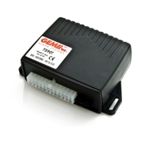
Details optimal placement for the control unit, considering water and interference.

Accessory Positioning

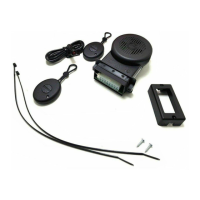
Guides on positioning various accessories like the electronic key receptacle and push-buttons.

Control Unit Sealing Procedure

Critical installation step detailing how to properly seal the control unit.

Electrical Connections Summary

Electric Diagram

Engine Immobilisation Diagram (Grounded Wire)

Engine Immobilisation Diagram (Cut Wire)

Engine Immobilisation Example (Specific Harness)

Specific Wiring Harness Connections

Engine Immobilisation Connection

Instructions for connecting the engine immobilisation feature using specific harness.

Turn Signals Connection

Guides on connecting the alarm system to the vehicle's turn signals.

Ground Connection

Details how to establish a ground connection when not available on the ignition switch.

Electronic Key Receptacle with LED

Instructions for connecting the electronic key receptacle and its LED.

Diode Application Instructions

Learning New Devices (Ground Connection)

Learning New Devices (No Ground Connection)

Extra Functions Programming

Programming Example

Shock Sensor Adjustment

Shock Sensor Adjustment Example

Declaration of Conformity

Related product manuals