EasyManua.ls Logo

Gemini GEM-P9600 - User Manual

Gemini GEM-P9600
68 pages
Print Icon
To Next Page IconTo Next Page
Loading...
INSTALLATION
INSTRUCTIONS
HARDWIRE WIRELESS
GEM-P9600
CONTROL PANEL/COMMUNICATOR
WI742D 5/03
© Napco 2003
R
"K Series" GEM-K2AS
R
COMPUTERIZED SECURITY SYSTEM
ARMED
STATUS
SYSTEM ARMED
01/01/97 12:00AM
12
4
3
56
7890
A
B
C
D
E
F
G
NEXT/YES
PRIOR/NO
AREA
GEMINI
READY
AC ON
READY
AC ON
R
R
COMPUTERIZED SECURITY SYSTEM
ARMED
STATUS
SYSTEM ARMED
01/01/97 12:00AM
12
4
3
56
7890
A
B
C
D
E
F
G
NEXT/YES
PRIOR/NO
AREA
GEMINI
ENT A1
32
INT ER IOR
BYPASS FIRE/TBL SYS TBL CHIME
"K Series" GEM-K3DGTL
R
For use with "Classic" keypads (GEM-RP1CAe2, GEM-RP2ASe2, GEM-RP3DGTL and GEM-RP4RFC/GEM-RP4C)
and with "K Series" keypads (GEM-K1CA, GEM-K2AS, GEM-K3DGTL, and GEM-K4RF/GEM-K4)
"K Series" GEM-K1CA
GEMINI
SYSTEM READY
01/01/03 12:00 AM
ARMED
COMPUTERIZED SECURITY SYSTEM
STATUS
R
1
2
3
B 4 5 6
C 7 8 9 0
U
NEXT/YES
P
PRIOR/NO
Q
AREA
G
"K Series" GEM-K4 / K4RF

Other manuals for Gemini GEM-P9600

Question and Answer IconNeed help?

Do you have a question about the Gemini GEM-P9600 and is the answer not in the manual?

Gemini GEM-P9600 Specifications

General IconGeneral
BrandGemini
ModelGEM-P9600
CategorySecurity System
LanguageEnglish

Summary

Changes From Previous Edition

Important Note

Introduction

General Description

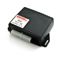
Overview of the GEM-P9600 as a state-of-the-art microcomputer-based burglary and fire alarm control panel.

Features

Details the extensive features of the GEM-P9600, including zone capabilities, user support, and output options.

Specifications

Optional Accessories and Peripherals

UL Listings

Lists the UL certifications for the control panel and related systems.

Compatible UL-Listed Devices

Provides a list of recommended devices compatible with UL-listed systems.

Summary of UL Requirements

Installation

Mounting

Guidance on selecting a location and mounting the control panel and keypads.

Tamper Switches

Instructions for installing tamper switches to secure the control panel.

Keypad

Instructions for mounting keypads near exit/entry doors.

Adding Expansion Zones

Wireless Systems

Typical Residential Fire Installation

Typical Partitioned Installation

UL Commercial-Burglary Installations

Testing the System

Signal Strength Testing;Wireless Systems

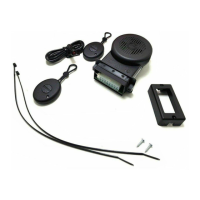
Procedure for testing wireless transmitter signal strength.

Wiring Connections

Battery

Wiring instructions for connecting the backup battery.

Transformer

Wiring instructions for connecting the AC power transformer.

Siren;Bell Burg;Fire Alarm Output

Wiring for connecting alarm sounding devices.

Auxiliary Alarm Output

Wiring for the auxiliary alarm output.

Remote Bus

Earth Ground

Auxiliary Power

Basic Zone Configuration

Expanded Zone Configuration

4-Wire Smoke Detectors

2-Wire Smoke Detectors

Telephone Lines

Keypad Configuration Mode

Keypad Installation

Information on installing keypads and assigning addresses.

Configuring the Keypads

Procedures for configuring keypads, including beep, sounder, and address.

Compatibility Number

EZM Address

Zone Response

Configuring Keypads

Basic Operation

User Codes & Zone Descriptions

Details on programming user codes and zone descriptions.

Arming and Disarming the System

How to arm and disarm the security system.

Arming

Disarming

Arming in STAY Mode

Instant Arming

Auto Arming

Priority Arming

Bypassing Zones

Selective Bypass

How to bypass specific zones on the system.

Alarm Indication

Function Mode;Dealer Program Mode

Display OP;CL

Activate Overview

Reset System Trbl

Activate Locate

Activate Dialer Test

Display RF Transmitter Stat

Relay Control

Keypad Messages

Glossary

Abort Delay

Delay to allow cancellation of central-station report by disarming before report is sent.

AC Failure

System trouble annunciated when AC power is removed.

Access Control

Functionality for opening/closing garage doors or activating electric strikes.

Alarm Outputs

Ambush Codes

Anti-Jam Time

Areas

Auto Bell Test on Arming

Battery

Bell Control

Call Waiting

Closing Report

Cold Start

Data Format

Modem Formats

Relay Control

Dial-Tone Detection

Digital Dialer Report Enter;Exit Test Mode

Disable Callback Download

Easy Arming

Enable Exit Delay Restart

Entry;Exit Delay

Expansion Zones

Fire

Jumpers

Key Fob Transmitters

Logging of Security Bypassed Zones

Loop Response

Low Battery

Master Security Code

Receiver Format

Priority Zone

Relay Control

Report Telco 1

Selective Bypass

Sensor Watch

Sound Alarm On Exit Error

Split Reporting

Swinger Shutdown

System Trouble Audible Automatic Timeout

Telemetry Trouble

Telephone Numbers

Time Selection

Trouble on a Burglary Zone

Veri-Phone

Zone ANDing

24-Hour Zone

Standby-Battery Calculation Worksheet

Wiring Legend

Keypad Programming Modes

Function Mode

Lists the available functions and required authority levels for keypad operation.

Dealer Mode

Easy Menu Program Mode

GEM-RP1 CAe2;GEM-K1 CA Keypads

GEM-P9600 Wiring Diagram

CP-01 Quick Reference Chart-SIA False Alarm Reduction

Duress Code

Enables the use of a code to trigger a silent alarm and report to central station.

System Test

Enables testing of zones, sounders, and communicator with Fault Find.

GEM-P9600 Factory Default Description

Statement for Canadian Models

FCC Statement

Napco Limited Warranty

Related product manuals