Do you have a question about the Gemini 932IT and is the answer not in the manual?
Details how to arm the system using original or Gemini remote controls.
Explains arming the system while excluding internal volumetric protection.
Details automatic system arming after ignition off and door closure.
Explains the 30-second delay before the system is fully armed.
Describes the state of the system after the arming delay.
Details alarm signaling, time between alarms, and alarm cycle duration.
Explains how to disarm the system using different remote controls.
Describes the use of the touch key for emergency override and disarming.
Explains how the LED indicates the last alarm event and lists causes.
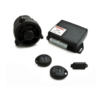
Details the two-button remote control and its battery replacement.
Details the four-button remote control and its battery replacement.
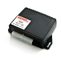
Lists wire functions and colors for the 20-pin main connector.
Lists wire functions and colors for the 8-pin secondary connector.
Explains system management via the vehicle's CAN BUS line.
Details connections to the door lock motor unit for arming/disarming.
Describes connecting to turn indicators for arming/disarming signals.
Covers combined connections using CAN, turn indicators, and door locks.
Explains how to activate optical signals (turn indicator flashes) for arming/disarming.
Explains how to activate acoustic signals (siren chirps) for arming/disarming.
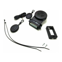
Details how to connect and position ultrasonic sensors.
Explains the procedure for adjusting the sensitivity of the ultrasonic sensors.
| Brand | Gemini |
|---|---|
| Model | 932IT |
| Category | Security System |
| Language | English |