1.0
2.0
4.0
11.0
12
13.0
14.0
15.0
- INTRODUCTORY NOTE...........................................................................................
- OPERATING INSTRUCTIONS...................................................................................
2.1 - Complete system arming..........................................................................................
2.2 - System arming with sensor exclusion......................................................................
2.3 - Passive arming.........................................................................................................
2.4 - Arming delay.............................................................................................................
2.5 - System armed..........................................................................................................
2.6 - Alarm, inhibit time between alarms and alarm cycles...............................................
2.7 - System disarming.....................................................................................................
2.8 - Emergency override via touch key............................................................................
2.9 - Alarm memory...........................................................................................................
- TWO-BUTTON REMOTE CONTROL - 7208E.........................................................
- FOUR-BUTTON REMOTE CONTROL - 848/ALG...................................................
- RFID TRANSPONDER - 908....................................................................................
- PINOUT TABLES........................................................................................................
4.1 - 20-pin connector.... ..................................................................................................
4.2 - 8-pin connector...... ..................................................................................................
.............................................................
6.4 - Combination connection...........................................................................................
....................................
....................................................................................
..... .........................................................
8.4 - Door switch polarity selection...................................................................................
8.5 - ..................................
...............................................
ADDING NEW DEVICES.......................... ...............................................................
- DELETING PROGRAMMED DEVICES....................................................................
..................................................
.....................................................................
................................................................................
- SYSTEM RESET......................................................................................................
- TECHNICAL SPECIFICATIONS...............................................................................
-
.................................................................................................
USER GUIDE
INSTALLER MANUAL
3.0
5.0
6.0
7.0
8.0
9.0
10.0
.0
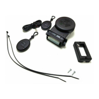
- OPTIONAL DEVICES AND BATTERY REPLACEMENT............................................
3.1
3.2
3.3
- WIRING DIAGRAM.....................................................................................................
- CONNECTIONS TO ARM/DISARM THE SYSTEM....................................................
6.1 - Connections and operation via CAN BUS line.........................................................
6.2 - Connections to locking motors.................................................................................
6.3 - Connections to turn indicators.....................
- VEHICLE CODE PROGRAMMING............................................................................
- SYSTEM PROGRAMMING....................................................
8.1 - Optical signals..........................................................................................................
8.2 - Acoustic signals....................
8.3 - Passive arming....... ....................................
Hazard warning lights or negative output during an alarm.....
- SYSTEM PROGRAMMING EXAMPLE.......................
-.
- ULTRASONIC VOLUMETRIC PROTECTION........
12.1 - Connections and positioning.............
12.2 - Sensor adjustment..................
WASTE ELECTRICAL AND ELECTRONIC EQUIPMENT
(WEEE) DIRECTIVE
PAGE 02
PAG. 03
PAG. 03
PAG. 03
PAG. 03
PAG. 04
PAG. 04
PAG. 04
PAG. 04
PAG. 04
PAG. 04
PAG. 05
PAG. 06
PAG. 08
PAG. 08
PAG. 08
PAG. 09
PAG. 10
PAG. 13
PAG. 13
PAG. 14
PAG. 15
PAG. 16
PAG. 16
PAG. 16
PAG. 06
PAG. 06
PAG. 07
PAG. 10
PAG. 10
PAG. 10
PAG. 10
PAG. 11
PAG. 12
PAG. 12
PAG. 12
PAG. 13
PAG. 13
PAG. 16
PAG. 17
PAG. 17
I
TABLE OF CONTENTS