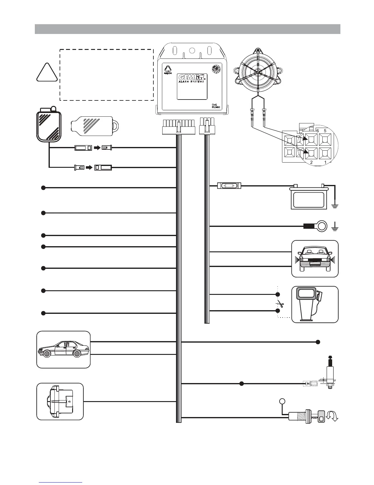
Battery
8A
MAX !
BLACK marked “M”
GROUND
POSITIVE
BLACK marked “R”
ORANGE
ORANGE
Output - Turn indicators
BLACK marked “G”
+30
Ignition
BLACK marked “H”
BLACK marked “H”
Engine immobilizer
GREEN
Bonnet switch
TOUCH KEY
5.0 - WIRING DIAGRAM
Connection to
supplied
siren
Before carrying out
electrical connections,
disconnect the battery
negative terminal and
reconnect again after
completion.
!
Red
Black
Green
Brown
1
567
234
8
Negative input - External sensors
Positive/negative input - Door switches
GREEN-BLACK
GREEN-BROWN
CAN BUS signal
LIGHT BLUE-GREY (CAN-H)
INSTALLER MANUAL - PAGE 09
LIGHT BLUE (CAN-L)
Lock command (negative)
Unlock comand (negative)
WHITE-BLACK
YELLOW-BLACK
Positive output -System armed (+A)
PINK
BLUE
Hazard lights or
negative output during alarm
(siren, pager, tracker)
YELLOW-BLUE
GREEN-BLUE
Input for system operation
via vehicle door
lock motor unit
WHITE-ORANGE
Input for system operation
via turn indicators