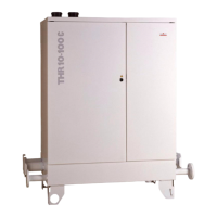
,167$//$7,21
(YDFXDWLRQ XVLQJ KRUL]RQWDO EDODQFHG
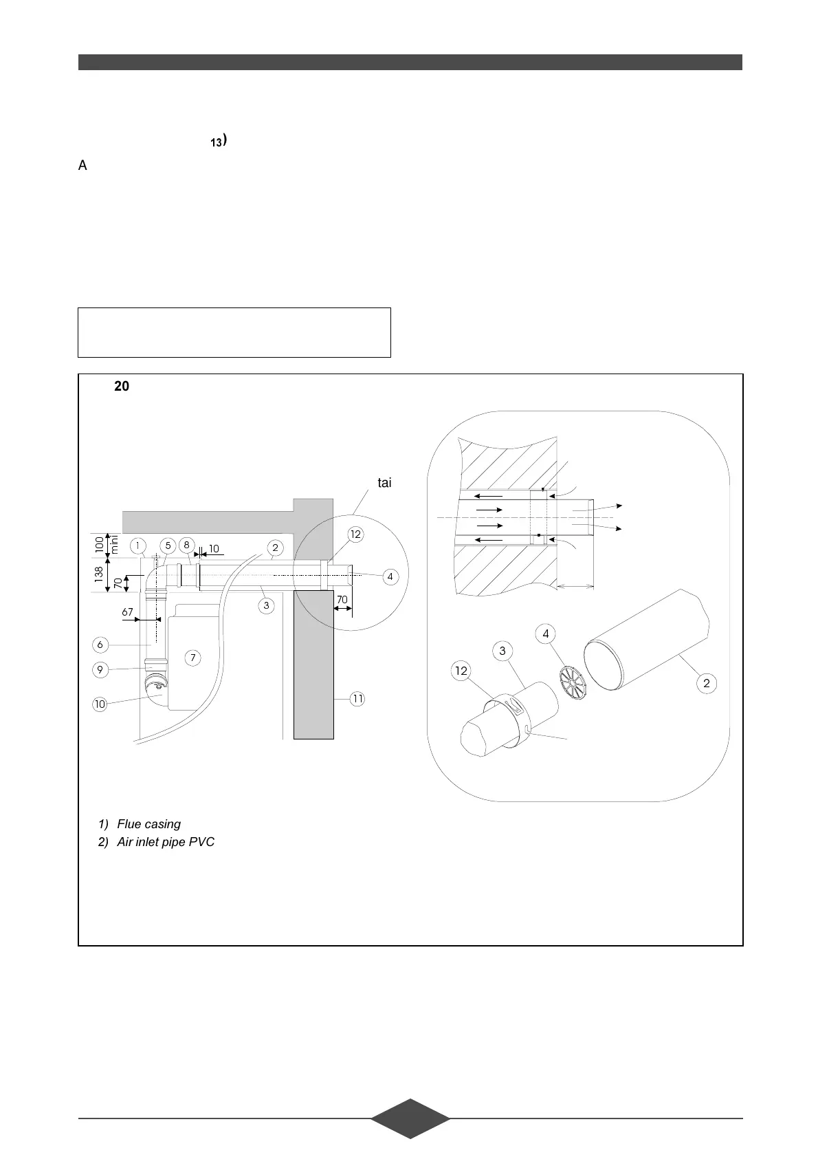
IOXHPRGHO&
A horizontal balanced flue must be installed when
the wall adjoining the water heater is on outside wall
in a well ventilated location. The water heater in-
stalled in this way possesses a sealed combustion
circuit, completely independent of the ventilation cir-
cuit for the rooms.
The flue may be mounted to the right, to the left, or
directly behind the water heater.
The balanced flue outlet must be located at least
0.4 m from any opening window and 0.6 m from any
air ventilation opening (see regulations). Two bal-
anced flue outlets (from two distinct adjacent THR
units) must be at least 0.6 m apart.
The flue gas exhaust tube must slope towards the
outside at 1 cm per meter to avoid accumulation of
rain water in the vent-air intake system.
Standard flue lenght: P
Maximum lenght: P
Detail A
Detail A
slot
pin
PP 80
∅
70
PVC 125
∅
P
L
Q
L
)LJ
)OXHFDVLQJ
$LULQOHWSLSH39&
&RPEXVWLRQSURGXFWRXWOHWWXEH33
6WDLQOHVVWHUPLQDO
HOERZ336ZLWKSUHVVXUHWHVWSRLQW
7XEH33O PP
+HDWLQJXQLW
7XEH336O PP
%ODFNHOERZ33
%ODFNHOERZ33
2XWVLGHZDOO
&HQWHULQJSLQ
 Loading...