Do you have a question about the geminox FCX 22 C and is the answer not in the manual?
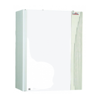
Overview of the FCX boiler's standardized features, components, and functions.
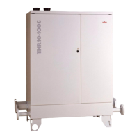
Details the available FCX models and their respective functions and flue connections.
Comprehensive table of technical data, including power, efficiency, dimensions, and electrical specs.
Specifies the required pipe diameters for various connections on the FCX boiler.
Provides detailed diagrams and measurements for the boiler's physical dimensions.
Identifies and labels all major components of the FCX boiler with numbered diagrams.
Details the specifications and performance curves of the boiler's circulating pump.
Presents characteristic curves for the mixing valve's operation and flow control.
Explains the function and specifications of the boiler's expansion vessel.
Identifies the specific GEMINOX oil burners used with the FCX models.
Illustrates the PCI thermal efficiency of the boiler relative to return temperature.
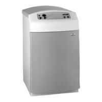
Describes the FCX boiler as a sealed exhaust circuit condensation unit with two heating circuits.
Covers general installation guidelines, location, and safety considerations for the boiler.
Outlines ventilation requirements for different flue types (B23, C13/C33).
Details flueing requirements and system compatibility for combustion products.
Guidelines for positioning the boiler concerning flue and hydraulic connections.
Specific instructions for using existing chimney flues with various accessories.
Installation example and requirements for B23 standard natural draft flue systems.
Installation example and requirements for B23p pressurized lining flue systems.
Installation example and requirements for C33 sealed flue systems.
Regulations and guidelines for installing balanced flue outlets.
GEMINOX recommendations and options for horizontal balanced flue installations.
Details the 0.95m straight horizontal flue kit for balanced flue systems.
Details the 3m angled horizontal flue kit for balanced flue systems.
Details the 3m angled horizontal flue kit with straight configuration.
Information on PPtl/PVC concentric extensions for flue systems.
Information on PPtl/PVC concentric elbows for flue systems.
Details the optional fastening collar for flue installations.
Details the adjustable support for flue installations.
Provides examples of balanced flue installations with different configurations.
Example installation of a straight balanced flue system.
Example installation of an angled balanced flue system with a hose.
Example installation of a rigid flue with an elbow for balanced flue systems.
Guidelines for drainage and terminal placement for vertical balanced flues.
Details the optional concentric vertical terminal for sloping roofs.
Details the optional sleeve tile with adaptable coupling for roof installations.
Information on PPtl/PVC concentric extensions for vertical flue systems.
Information on PPtl/PVC concentric elbows for vertical flue systems.
Details the optional polypropylene roof plate for flue systems.
Details the optional fastening collar for vertical flue extensions.
Details the adjustable support for vertical flue systems.
Examples of flue installations with bends at the boiler outlet.
Example installation with a straight configuration at the boiler outlet.
Another example installation with a straight configuration at the boiler outlet.
Examples of flue installations with boiler outlet extensions.
Example installation with a straight configuration and an outlet extension.
Example installation with elbows and an outlet extension.
Guidelines and precautions for connecting and maintaining the condensate drain.
Instructions for assembling standard accessories provided with the boiler.
Specific instructions for fitting the bleed and bend components.
Instructions for fitting 1" Ø 22 bends and seals to the boiler outlet/return.
Information on the optional hydraulic connection kit for DHW production systems.
General recommendations and considerations for hydraulic connections.
Specific recommendations from GEMINOX for hydraulic installations.
Discusses isolation valves, circulating pump, safety valve, and expansion vessel.
Diagram and explanation for connecting FCX models to a single heating circuit.
Diagram for connecting FCX+BS DHW system to a single heating circuit.
Diagram explaining the hydraulic connection for FCX models to a double heating circuit.
Diagram for connecting FCX+BS DHW system to a double heating circuit.
Details on making the oil connection to the burner.
General information and safety requirements for electrical connections.
Instructions for connecting the boiler to the main power supply.
Steps for making electrical connections to the boiler's terminal box.
Wiring schematic for a system without a regulator.
Wiring schematic for a room thermostat controlling the heating pump.
Wiring schematic for a room thermostat controlling the mixer valve.
Notes on analogue and digital controls and their relation to climatic conditions.
Provides a general electrical principle schematic for the boiler's control system.
Detailed wiring schematic showing connections to the installation and accessories.
Recommends specific water conditioning products for system protection.
Details Bionibal as a biocide, corrosion inhibitor, and its dosage.
Details Bionibagel as an antifreeze and corrosion inhibitor, and its dosage.
Advises referring to manufacturer's recommendations for equivalent products.
Step-by-step instructions for filling the boiler and heating system with water.
Precautions for filling the oil tank before burner activation.
List of checks to perform before commissioning the boiler.
Installer's duty to inform the user about safety devices and maintenance.
General steps for commissioning the boiler.
Detailed steps for commissioning the boiler without a regulator.
Guidance for commissioning the boiler when a regulator is present.
Procedures and checks for commissioning the oil burner.
Instructions for verifying the proper functioning of safety and control devices.
Step-by-step guide for cleaning the internal walls of the boiler shell.
Instructions for cleaning the condenser and checking combustion product flow.
Recommendations for annual burner maintenance and cleaning.
Annual checks for safety devices, accessories, and potential leaks.
Procedure for checking and adjusting the expansion vessel's pre-inflation pressure.
Guidelines for checking, cleaning, and maintaining combustion product flues.
Instructions for cleaning the oil filter annually or as needed.
Detailed guide on replacing thermostats and thermometers in the boiler.
Specific instructions for accessing and replacing bulbs in the boiler shell pockets.
Specific instructions for accessing and replacing the bulb on the heating output tube.
Specific instructions for accessing and replacing the bulb in the condenser pocket.
General safety and procedural steps for replacing thermostats/thermometers.
Instructions for draining the boiler and heating system.
Identifies common causes for burner shutdown and manual reset procedures.
Explains shutdowns caused by overheating thermostats and reset methods.
Details the water overheating safety thermostat's function and reset.
Details the combustion product overheating safety thermostat's function and reset.
Official declaration of conformity to relevant EC directives and standards.