- 16 -
INSTALLATION
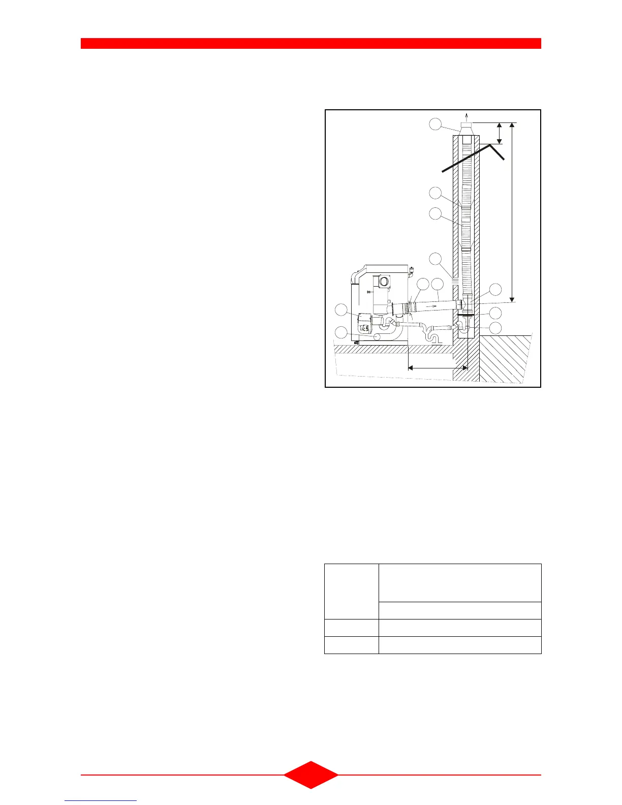
3.2.3 - Configuration with pressurized lining
(B
23p
)
Definition : Lining of an existing chimney flue by a
corrugated PP flue conduit of
∅ 110 according to
the height.
- The termination, specific to this configuration and
specified in the DTA, must have its outlet above
the roof (comply with the specification of the de-
cree of 22 October 1969),
- Do not use the hose for a horizontal assem-
bly: condensate may be retained.
- Fit a siphon (5) with a minimum 80 mm seal be-
tween the bleed T-bracket and the waste water
pipe,
- The bleed T-bracket at the foot of the flue is op-
tional when the vertical flue is short (L1 < 5 m),
- Ventilation for the flue (rep. 8) and the heating
system
(section 2 - chapter IV - INSTALLA-
TION) must be provided.
- If the boiler is installed in premises that have me-
chanical air extraction, ensure that this does not
cause negative pressure.
- The premises must never be fitted with other ap-
pliances using natural draft to operate.
- The air is sucked in by the burner directly from the
room in which the boiler is fitted.
- The burner must be equipped with the air damper
(item no. 2) in order to prevent heat losses due to
draft.
3.2.3.1 - Installation example
Accessories :
1) PPtl off-centre reduction
∅
80/110 (supplied with the
bleed T-bracket),
2) Air choke (supplied with the air damper kit),
3) PPtl tube
∅
110 L = 1 m (cut to the length required),
4) Bleed T-bracket
∅
110 (supplied with the off-centre re-
duction)
5) Siphon,
6) PP corrugated flue
∅
110,
7) Termination (above the roof)
8) Lining ventilation
9) Bleed T-bracket support
10)Chimney spacers
Note:
- Calculation of the diameters for the conduits to be
made according to EC standard EN 13 384-1.
- Each 45° elbow added reduces the total length al-
lowed by 0.5 m.
Models
Maximum permitted length L1 with
bleed T-bracket with horizontal
connection 1 m at conduit diameter
Conduit ∅ 110
FCX 22 C 20 m
FCX 30 C 15 m
6
4
1
3
8
21
2
L1
0,4 m
7
FCX-52-0
L2 = 1 m
maxi
9
5
10
Fig. 15
 Loading...