&200,66,21,1*
*$6&2
&212
;
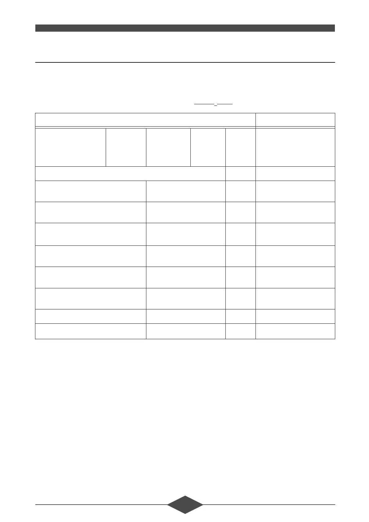
)/2:&+(&.
Select the regulator off position (“7” flashing - § 3.7.3
- III - OPERATION), then check the following combus-
tion parameters at maximum and minimum power.
Hot water potentiometer at left hand stop point =
P min., at right hand stop point = P max.
Adjust the gas flow using an analyser to obtain the
CO/CO
2
rates shown in the table:
Combustion product evacuation conduit back-pres-
sure: 0 mmWG.
The values of P1 and P2 may be higher or lower de-
pending on whether the back pressure is higher or
lower.
7\SH7+5 7+5
Heat output
30/50 °C
30/50 °C
60/80 °C
60/80 °C
B
23
C
13
/C
33
B
23
C
13
/C
33
min./max.
min./max.
min./max.
min./max.
kW
kW
kW
kW
10,6/50,5
10,6/47,8
9,5/47,0
9,5/44,5
Max. Heat input kW 10,0/50,0
Ø Gas reducer Natural gas H
Propane
mm
mm
7,30
5,60
Ø Air ring Natural gas H
Propane
mm
mm
-
31
Gas flow (15 °C 1013 mbar) Natural gas G20
Propane G31
m
3
/h
kg/h
1,06/5,29
0,776/3,881
Gas Pressure P2 Natural gas H
Propane
mbar
mbar
0,40/6,00
0,40/6,20
Servo-air pressure (PL) Natural gas H
Propane
Pa
Pa
40/610
40/630
CO
2
Natural gas H
Propane
%
%
7,5-8,0/9,0-9,5
10,0-10,5/10,5-11,0
CO Natural gas H ppm 0/20
No
x
Natural gas H
ppm 20/25
 Loading...